ZyXEL Communications ZyXEL Dimension ES-2024PWR User Manual
Page 256
Chapter 73 Additional Commands
Ethernet Switch CLI Reference Guide
256
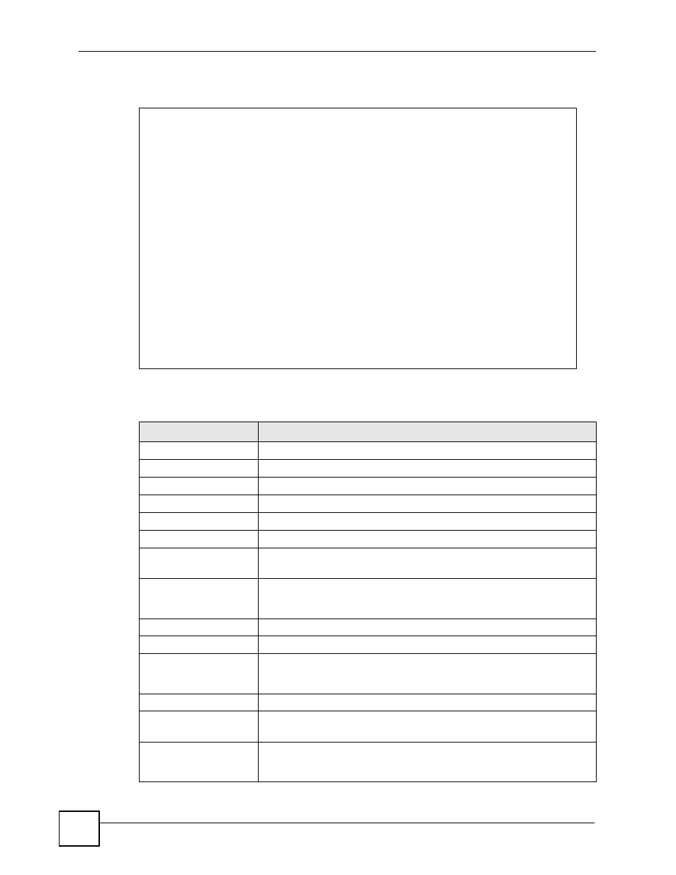
This example looks at the current sensor readings from various places in the hardware.
The following table describes the labels in this screen.
sysname# show hardware-monitor C
Temperature Unit : (C)
Temperature(%c) Current Max Min Threshold Status
--------------- ------- ----- ----- --------- ------
CPU 33.0 35.0 28.0 85.0 Normal
MAC 31.0 33.0 27.0 75.0 Normal
LOCAL 33.0 34.0 28.0 75.0 Normal
FAN Speed(RPM) Current Max Min Threshold Status
-------------- ------- ---- ---- --------- ------
FAN1 7356 7769 6569 3000 Normal
FAN2 6087 6279 6020 3000 Normal
FAN3 6157 6301 6067 3000 Normal
Voltage(V) Current Max Min Threshold Status
---------- ------- ----- ----- --------- ------
1.25VIN 1.243 1.256 1.243 +/-6% Normal
1.8VIN 1.869 1.880 1.869 +/-6% Normal
3.3VIN 3.372 3.398 3.372 +/-6% Normal
2.5VIN 2.593 2.593 2.593 +/-6% Normal
Table 155 show hardware-monitor
LABEL
DESCRIPTION
Temperature Unit
This field displays the unit of measure for temperatures in this screen.
Temperature
This field displays the location of the temperature sensors.
Current
This field displays the current temperature at this sensor.
Max
This field displays the maximum temperature measured at this sensor.
Min
This field displays the minimum temperature measured at this sensor.
Threshold
This field displays the upper temperature limit at this sensor.
Status
Normal: The current temperature is below the threshold.
Error: The current temperature is above the threshold.
FAN Speed(RPM)
This field displays the fans in the Switch. Each fan has a sensor that is
capable of detecting and reporting when the fan speed falls below the
threshold.
Current
This field displays the current speed of the fan at this sensor.
Max
This field displays the maximum speed of the fan measured at this sensor.
Min
This field displays the minimum speed of the fan measured at this sensor. It
displays "<41" for speeds too small to measure. (See the User’s Guide to
find out what speeds are too small to measure in your Switch.)
Threshold
This field displays the minimum speed at which the fan should work.
Status
Normal: This fan is running above the minimum speed.
Error: This fan is running below the minimum speed.
Voltage(V)
This field displays the various power supplies in the Switch. Each power
supply has a sensor that is capable of detecting and reporting when the
voltage is outside tolerance.