Toshiba H1 SERIES TLCS-900 User Manual
Page 44
TMP92CM22
2007-02-16
92CM22-42
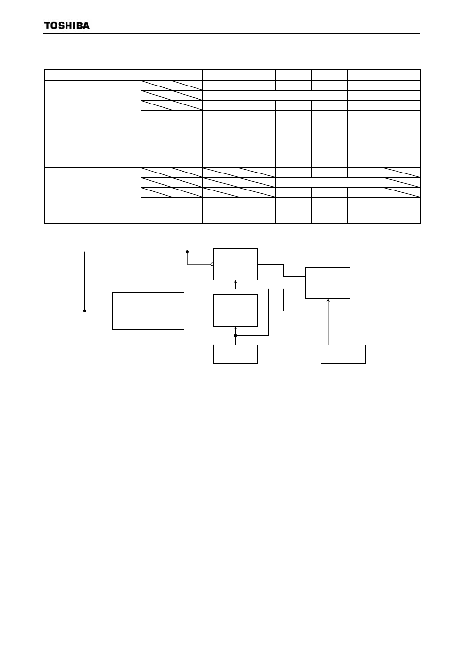
(2) External interrupt control
Symbol
Name
Address
7
6 5 4 3 2 1 0
I3EDGE
I2EDGE
I1EDGE
I0EDGE
I0LE
NMIREE
W
R/W
0 0 0 0 0 0
IIMC
Interrupt
input
mode
control
00F6H
(Prohibit
RMW)
INT3EDGE
0: Rising/
high
1: Falling/
low
INT2EDGE
0: Rising/
high
1: Falling/
low
INT1EDGE
0: Rising/
high
1: Falling/
low
INT0EDGE
0: Rising/
high
1: Falling/
low
INT0
0: Edge
1: Level
NMI
0: Falling
edge
1: Falling
and
rising
edges
I3LE I2LE I1LE
W
0 0 0
IIMC2
Interrupt
input
mode
control2
00FAH
(Prohibit
RMW)
INT3
0: Edge
1: Level
INT2
0: Edge
1: Level
INT1
0: Edge
1: Level
Note 1: Disable INT0 to INT3 before changing INT0 to 3 pins mode from “level” to “edge”.
Setting example for case of INT0:
DI
LD (IIMC) ,XXXXXX0-B
;
Change from “level” to “edge”.
LD (INTCLR),0AH
;
Clear interrupt request flag.
NOP
;
Wait EI execution.
NOP
NOP
EI
X: Don’t care,
−: No change
Note 2: See electrical characteristics in section 4 for external interrupt input pulse width.
Note 3: When release halt by INT0 to INT3 interrupt of level-mode in interrupt request enable, keep setting level by
isn’t processed correctly.
Example:
Case of set “H” level interrupt (
= 1,
Keep “H” level until be started interrupt process. If changed to “L” level before interrupt process starting,
interrupt isn’t processed correctly.
Detect edge
Rising
Falling
H level
L level
Level
edge
IxLE
IxEDGE