5 support for irda mode – Toshiba H1 SERIES TLCS-900 User Manual
Page 171
TMP92CM22
2007-02-16
92CM22-169
3.9.5
Support for IrDA Mode
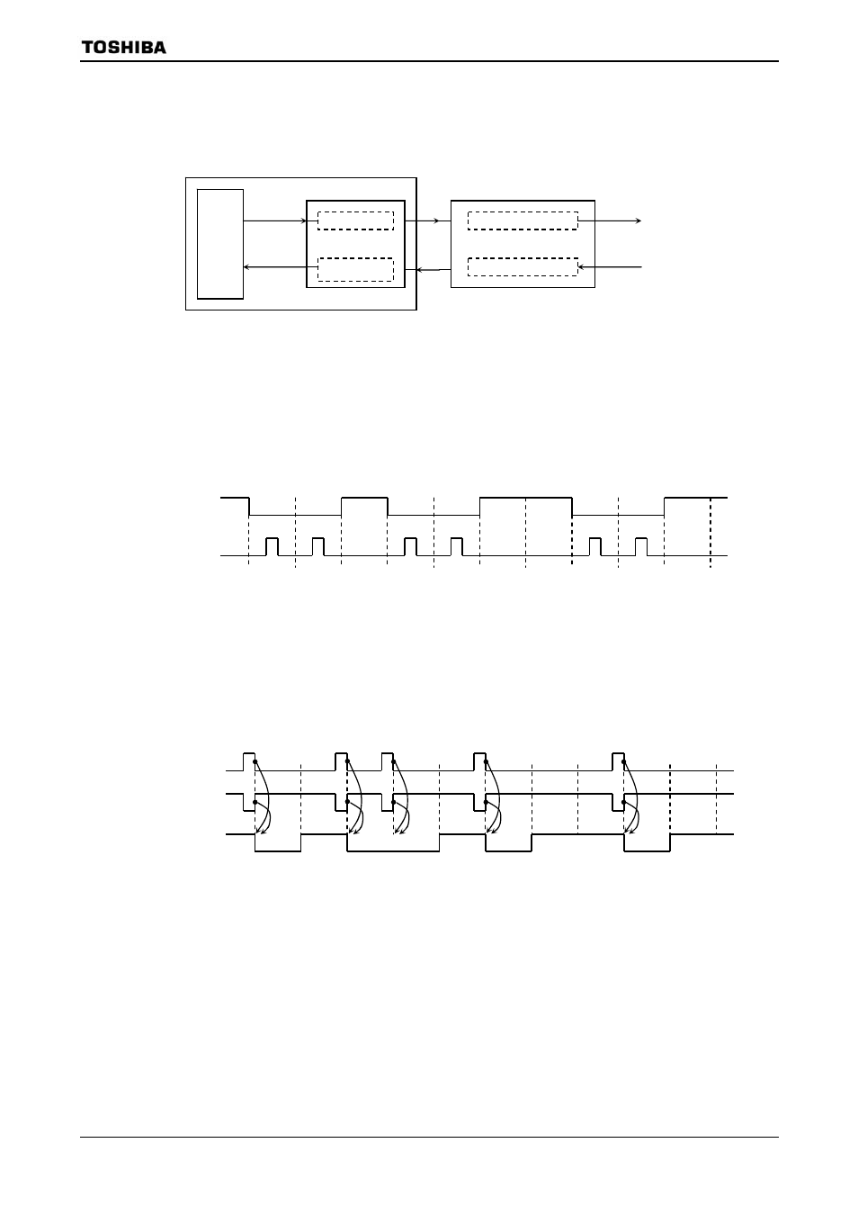
SIO0 includes support for the IrDA 1.0 infrared data communication specification.
Figure 3.9.24 shows the block diagram.
Figure 3.9.24 Block Diagram of IrDA
(1) Modulation of transmission data
When the transmission data is 0, output “H” level with either 3/16 or 1/16 times for
width of baud-rate (Selectable in software). When data is “1”, modem output “L” level.
Figure 3.9.25 Example of Modulation of Transmission Data
(2) Modulation of receiving data
When the receive data has the effective high level pulse width (Software selectable),
the modem outputs “0” to SIO0. Otherwise modem outputs “1” to SIO0. Receive pulse
logic is selectable by SIRCR
Figure 3.9.26 Example of Modulation of Receiving Data
Transmission
data
SIO0
IR modulator
IR
demodulator
Receive
data
IR transmitter & LED
IR receiver
Modem IR
module
TXD0
RXD0
IR output
IR input
TMP92CM22
Start
Transmission
data
Stop
0
0
0
0
1
0 1
1
Output after
modulation
Start
Data after
modulation
Stop
1
1
0
0
1 0
1
0
Receiving pulse
= “0”
Receiving pulse
= “1”