Installation and wiring, Caution, 3 wiring terminals – Toshiba 6F3B0253 User Manual
Page 59: Basic hardware and function, 16 awg) i/o signals 0.3mm, 18 awg)
6F3B0253
Basic Hardware and Function
57
4. Installation and Wiring
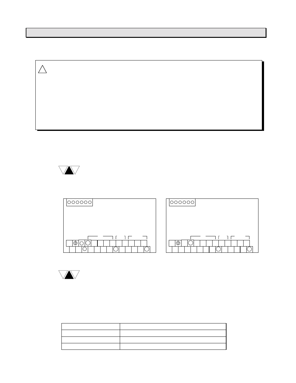
4.3 Wiring terminals
The terminal screw size of the T1-16S is M3. Use crimp-style terminals of 7mm width
or less useable for M3. The terminal block is not removable (fixed).
For input and output signal connections, refer to sections 2.4 and 3.
T1-MDR16SS .... AC power supply model
T1-MDR16SSD.. DC power supply model
3
1
0
L
4
2
NC
N
MDR16SS
DC OUT
−
+
24
22
20
6
23
21
Vin
7
5
26
27
25
C
C
C
RELAY OUT
DC IN
RS-485 (Enhanced model only)
3
1
0
+
4
2
NC
-
MDR16SSD
DC OUT
NC
NC
24
22
20
6
23
21
Vin
7
5
26
27
25
C
C
C
RELAY OUT
DC IN
RS-485 (Enhanced model only)
TXA RXA RXB
TXB TRM SG
TXA RXA RXB
TXB TRM SG
(1) NC stands for ”no connect”. Do not use the NC terminals for wire
relaying or branching.
(2) For the connections of the RS-485 communication port (the upper
terminal block), refer to the separate manual “T1-16S User’s Manual -
Communication Function -.
The applicable wire size is 0.3mm
2
(22 AWG) to 1.25mm
2
(16 AWG). The table below
shows the recommended wire size.
Type of signal
Recommended wire size
Power
1.25mm
2
(16 AWG)
Grounding
1.25mm
2
(16 AWG)
I/O signals
0.3mm
2
(22 AWG) to 0.75mm
2
(18 AWG)
!
CAUTION
1. Turn off power before wiring to minimize the risk of electrical shock.
2. Exposed conductive parts of wire can cause electrical shock. Use
crimp-style terminals with insulating sheath or insulating tape to cover
the conductive parts. Also close the terminal covers securely on the
terminal blocks when wiring has been completed.
3. Turn off power before removing or replacing units, modules, terminal
blocks or wires. Failure to do so can cause electrical shock or damage
to the T1-16S and related equipment.
NOTE
NOTE