Special i/o functions – Toshiba 6F3B0253 User Manual
Page 275
6F3B0253
Basic Hardware and Function
273
8. Special I/O Functions
8.7 PWM output function
Function
This function is used to output a variable duty cycle pulse train. The controllable duty
cycle is 0 to 100 % (1 % units).
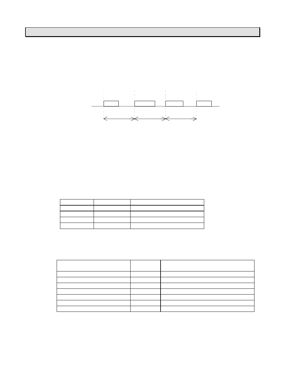
ON duty
50%
70%
60%
PWM
T
T
T
T = Pulse cycle
The PWM output is enabled when the pulse enable flag is ON. While the pulse enable
flag is ON, the duty cycle (ON duty) can be changed by changing the duty setting
value (0 to 100).
The frequency setting is available in the range of 50 to 5000 Hz (1 Hz units) before
turning ON the pulse enable flag. The frequency changing is not allowed while the
pulse enable is ON.
Note that the minimum ON/OFF pulse duration is 100
µ
s. Therefore, the controllable
ON duty range is limited depending on the frequency setting as follows. If the ON duty
setting value is not available (within 0 to 100), the pulse width error flag comes ON.
(PWM output operation is continued but the duty cycle is not guaranteed)
Frequency
Cycle time
Available ON duty
50 - 100 Hz
20 - 10 ms
0 to 100 %
200 Hz
5 ms
0, 2 to 98, 100 %
1000 Hz
1 ms
0, 10 to 90, 100 %
5000 Hz
200
µ
s
0, 50, 100 %
Related registers
SW26: Function selection. Refer to section 8.1.
Function
Register/
device
Remarks
PWM pulse
Y020
Pulse enable flag
S270
Output is enabled when ON
Frequency setting register
SW28
Data range: 50 to 5000
ON duty setting register
SW29
Data range: 0 to 100
Pulse width error flag
S26D
ON at error (reset OFF automatically)
ON duty setting error flag
S26E
ON at error (reset OFF automatically)
Frequency setting error flag
S26F
ON at error (reset OFF automatically)
Note) If the setting value of SW28 or SW29 is out of the allowable range, the
frequency setting error flag (S26F) or the ON duty setting error flag (S26E)
comes ON. (PWM output operation is continued with previous ON duty setting)