Toshiba 6F3B0253 User Manual
Page 167
6F3B0253
Basic Hardware and Function
165
7. Instructions
FUN 069
SHL1
1 bit shift left
Expression
Input
−
[ SHL1 A ]
−
Output
Function
When the input is ON, the data of register A is shifted 1 bit to the left (MSB direction). 0 is stored in
the right most bit (LSB). The pushed out bit state is stored in the carry flag (CF = S050). After the
operation, if the left most bit (MSB) is ON, the output is turned ON.
Execution condition
Input
Operation
Output
CF
OFF
No execution
OFF
−
ON
Execution
When MSB = 1
ON
Set or reset
When MSB = 0
OFF
Set or reset
Operand
Name
Device
Register
Constant Index
X
Y
R
S
T.
C. XW YW RW SW T
C
D
I
J
K
A Operation data
√
√
√
√
√
√
√
√
√
√
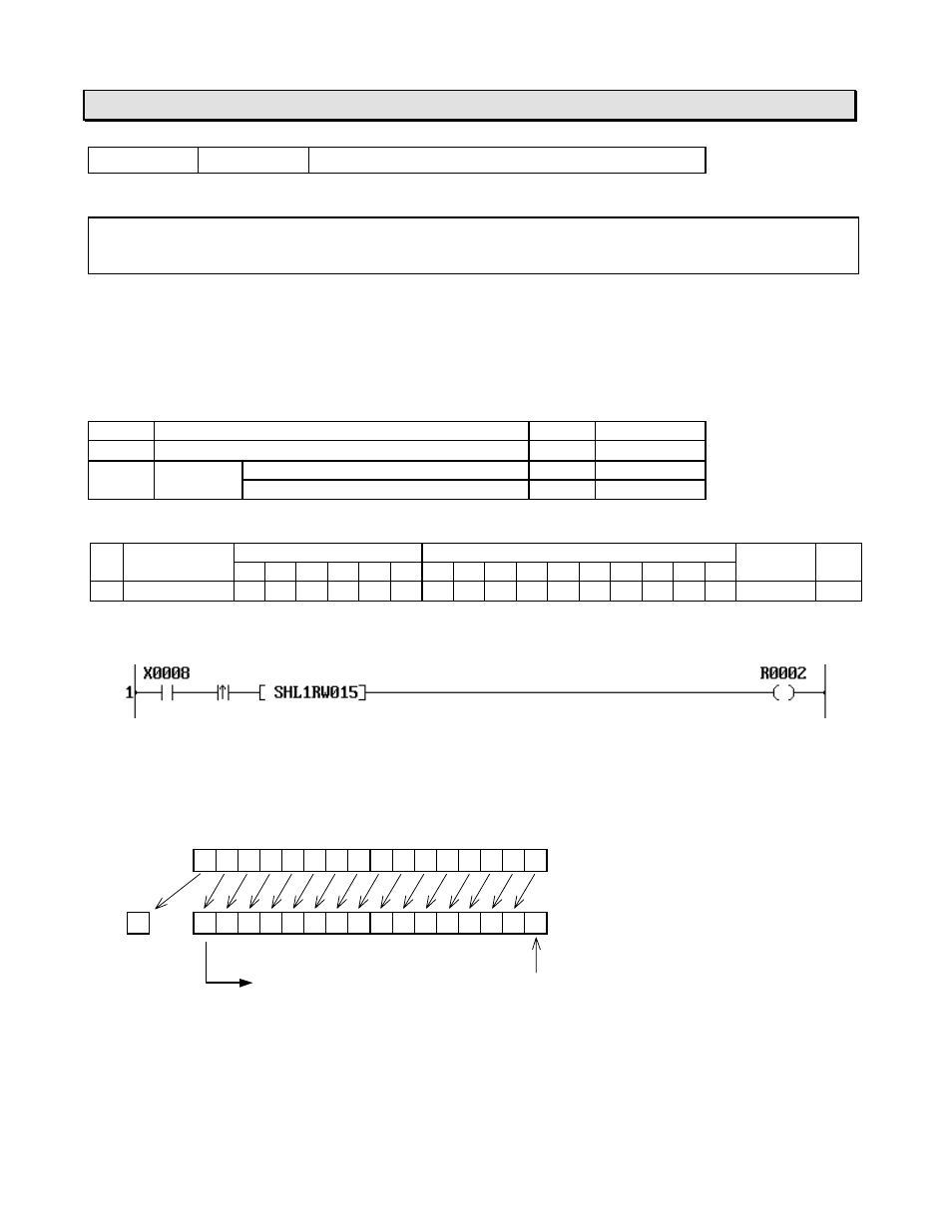
Example
When X008 is changed from OFF to ON, the data of RW15 is shifted 1 bit to the left.
The figure below shows an operation example.
(MSB)
(LSB)
F
E
D
C
B
A
9
8
7
6
5
4
3
2
1
0
1 1 1 0 0 1 1 1 0 0 1 1 1 0 1 0
CF
1
1 1 0 0 1 1 1 0 0 1 1 1 0 1 0 0
R002 is turned ON
0
RW15
RW15 (Result)