Instructions – Toshiba 6F3B0253 User Manual
Page 250
6F3B0253
248
T1-16S User’s Manual
7. Instructions
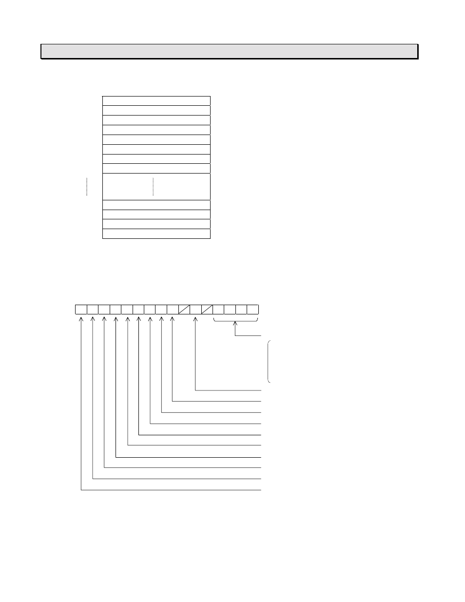
Data table:
Register
Data contents
Signal direction
D2000
#0 Operating frequency
←
Read
D2001
#0 Output terminal status
←
Read
D2002
#0 Frequency reference
→
Write
D2003
#0 Operation command
→
Write
D2004
#1 Operating frequency
←
Read
D2005
#1 Output terminal status
←
Read
D2006
#1 Frequency reference
→
Write
D2007
#1 Operation command
→
Write
D2020
#5 Operating frequency
←
Read
D2021
#5 Output terminal status
←
Read
D2022
#5 Frequency reference
→
Write
D2023
#5 Operation command
→
Write
•
The data format for the operating frequency and the frequency reference registers are 0.01 Hz units.
For example, if it is 60 Hz, the corresponding register data is 6000.
•
For the data format of the output terminal status register, refer to the Monitor mode (mode 1).
•
The bit assignment of the operation command register is as follows. For details, refer to your
Inverter manual.
F
E
D
C
B
A
9
8
7
6
5
4
3
2
1
0
Programmed speed selection
0000 = None
0001 = Speed 1
0010 = Speed 2
:
1111 = Speed 15
PI operation (0 = Normal / 1 = Off)
DC braking (0 = Off / 1 = On)
Jog operation (0 = off / 1 = On)
F/R selection (0 = Forward / 1 = Reverse)
Run/Stop (0 = Stop / 1 = Run)
Free run (0 = Normal / 1 = Free run)
Emergency stop (0 = Normal / 1 = EMS)
Reset command (0 = Normal / 1 = Reset)
Frequency enable (0 = Disable / 1 = Enable)
Command enable (0 = Disable / 1 = Enable)
Example operation:
To operate the #0 Inverter at 30 Hz forward rotation, write the value 3000 in D2002 and HC400 in
D2003. (HC400 = Bits F, E, A are 1, and others are 0)
The current operating frequency and the output terminal status of the #0 Inverter are stored in D2000
and D2001 respectively.