Instructions fun 091 dpx demultiplexer – Toshiba 6F3B0253 User Manual
Page 179
6F3B0253
Basic Hardware and Function
177
7. Instructions
FUN 091
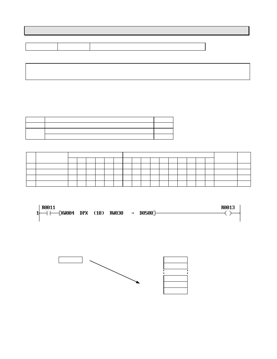
DPX
Demultiplexer
Expression
Input
−
[ A DPX (n) B
→
C ]
−
Output
Function
When the input is ON, the data of A is transferred to the register which is designated by B in the
table, size n starting with C.
Execution condition
Input
Operation
Output
OFF
No execution
OFF
ON
Normal execution
OFF
Pointer over (no execution)
ON
Operand
Name
Device
Register
Constant Index
X
Y
R
S
T.
C. XW YW RW SW T
C
D
I
J
K
A Source
√
√
√
√
√
√
√
√
√
√
√
n Table size
1 - 64
B Pointer
√
√
√
√
√
√
√
√
√
√
0 - 63
C Start of table
√
√
√
√
√
√
Example
When R011 is ON, the data of XW04 is transferred to the register which is designated by
RW30 in the table D0500 to D0509 (10 registers size).
If the data of RW30 is 8, XW04 data is transferred to D0508.
Source
Destination table
Pointer
XW04
3210
D0500
0
D0501
1
D0507
7
D0508
3210
8
D0509
9
Note
•
If the pointer data designates outside the table (10 or more in the above example), the transfer
is not executed and the output comes ON.
•
The table must be within the effective range of the register address.