Instructions – Toshiba 6F3B0253 User Manual
Page 252
6F3B0253
250
T1-16S User’s Manual
7. Instructions
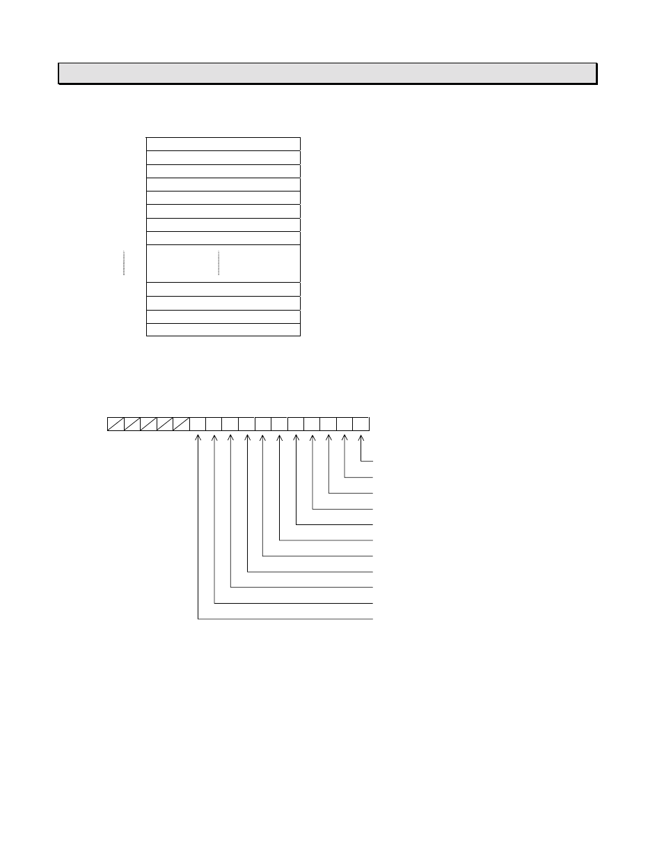
Data table:
Register
Data contents
Signal direction
RW100
#0 Operating frequency
←
Read
RW101
#0 Output terminal status
←
Read
RW102
No use
RW103
No use
RW104
#1 Operating frequency
←
Read
RW105
#1 Output terminal status
←
Read
RW106
No use
RW107
No use
RW176
#19 Operating frequency
←
Read
RW177
#19 Output terminal status
←
Read
RW178
No use
RW179
No use
•
The data format for the operating frequency register is 0.01 Hz units. For example, if it is 60 Hz, the
corresponding register data is 6000.
•
The bit assignment of the output terminal status register is as follows. For details, refer to your
Inverter manual.
F
E
D
C
B
A
9
8
7
6
5
4
3
2
1
0
OUT1 (f130)
OUT2 (f131)
FL (f132)
R1 (f133)
R2 (f134)
OUT3 (f135)
OUT4 (f136)
ALM0
ALM1
ALM2
ALM3
Example operation:
The current operating frequency and the output terminal status of the #0 Inverter are stored in RW100
and RW101 respectively.
If the #0 Inverter is operating at 55 Hz, the data 5500 is stored in RW100. If the OUT2 terminal of the
#0 Inverter is ON, the bit 1 of RW101 (R1011) becomes 1.