Special i/o functions – Toshiba 6F3B0253 User Manual
Page 259
6F3B0253
Basic Hardware and Function
257
8. Special I/O Functions
Mode setting for the special I/O functions
These functions, except the analog setting function, are selected by setting data into
SW16 and SW26 by user program. These registers work as mode setting registers for
the special I/O functions. The data setting for these registers, i.e. mode setting for the
special I/O functions, is effective only at the first scan.
Note) In the explanation below, HSC and INT mean the high speed counter and the
interrupt input functions respectively.
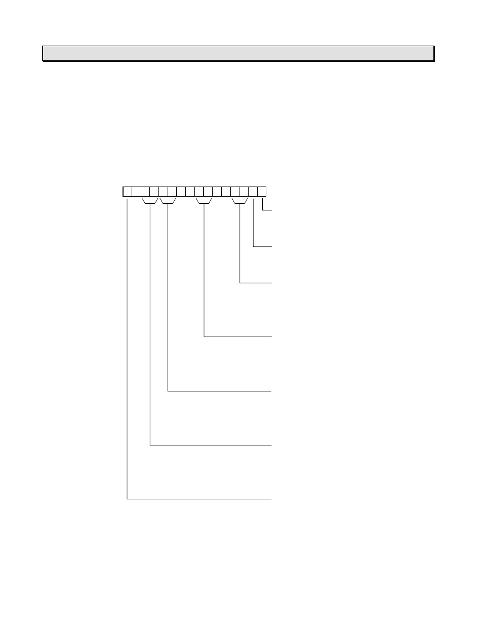
F E D C B A 9 8 7 6 5 4 3 2 1 0
SW16
0
0 0
0 0
Bit 0 < HSC and INT master flag >
0: No use
1: Use
Bit 1 < HSC / INT selection >
0: INT
1: HSC
Bits 2 and 3 < INT No.1 mode >
00: No use (Reserve)
01: Rising (OFF to ON)
10: Falling (ON to OFF)
11: No use (Reserve)
Bits 6 and 7 < INT No.2 mode >
00: No use (Reserve)
01: Rising (OFF to ON)
10: Falling (ON to OFF)
11: No use (Reserve)
Bits A and B < HSC mode >
00: Single phase up-counter
01: Single phase speed-counter
10: Quadrature bi-pulse counter
11: No use (Reserve)
Bits C and D < Enable flag for HSC / INT >
00: CH2 - disable, CH1 - disable
01: CH2 - disable, CH1 - enable
10: CH2 - enable, CH1 - disable
11: CH2 - enable, CH1 - enable
Bit F < Variable input filter constant >
0: No use (fixed to 10ms)
1: Use