Toshiba 6F3B0253 User Manual
Page 247
6F3B0253
Basic Hardware and Function
245
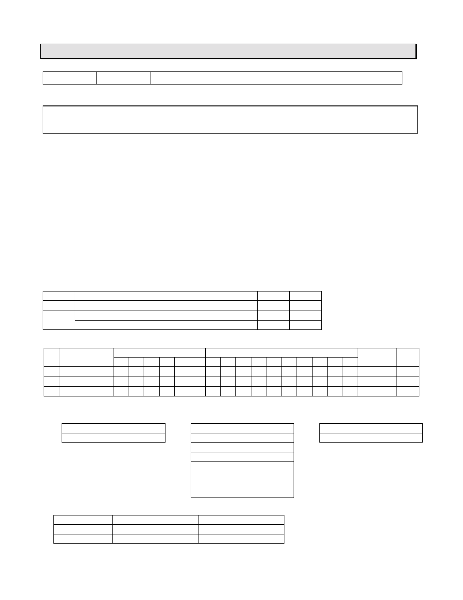
7. Instructions
FUN 236
XFER
Expanded data transfer (Inverter connection mode)
Expression
Input
−
[ A XFER B
→
C ]
−
Output
Function
This function is provided to control Toshiba Inverters VF-A7/G7/S9 connected on the RS-485 line.
When the RS-485 port operation mode is set to the Inverter mode (SW56 = 3), the T1-16S can
perform the following functions for up to 63 Inverters.
(1) Cyclically scans the Inverters and sends/receives the following data to/from each Inverter.
•
Send to Inverter: Frequency reference write and Operation command write (Run, Stop, etc.)
•
Receive from Inverter: Operating frequency monitor and Output terminal status monitor
(2) Cyclically scans the Inverters and receives the following data from each Inverter.
•
Receive from Inverter: Operating frequency monitor and Output terminal status monitor
(3) Sends a specified Read command to a specified Inverter and stores the response data.
(4) Sends a specified Write command with the command data to a specified Inverter.
(5) Sends a specified Write command with the command data to all the connected inverters as
broadcast.
Execution condition
Input
Operation
Output
ERF
OFF
No execution
OFF
−
ON
Normal execution
ON
−
When error is occurred (see Note)
ON
Set
Operand
Name
Device
Register
Constant Index
X
Y
R
S
T.
C. XW YW RW SW T
C
D
I
J
K
A Data table
√
√
√
√
√
√
√
B Inverter No.
√
√
√
√
√
√
√
C RS-485 port
√
√
√
√
√
√
Parameters
Data table designation
Parameter and status
RS-485 port designation
A
Register type code
B
Inverter number
C
Fixed to H0030
A+1
Leading address
B+1
Operation mode
C+1
Fixed to 0
B+2
Execution status
B+3
Communication error code
B+4
Inverter communication
B+5
status map
B+6
(each bit shows each
B+7
Inverter status)
Data table designation (A, A+1):
Register
Type code (A)
Leading address (A+1)
RW register
H0003
0 to 255
D register
H0004
0 to 4095