Philips V24CT User Manual
Page 344
Controls and Connectors
11-28 Monitor Installation and Patient Safety
M
onitor
Ins
ta
lla
ti
on
a
nd Pa
ti
e
n
t Sa
fe
ty
M1095A Display Module
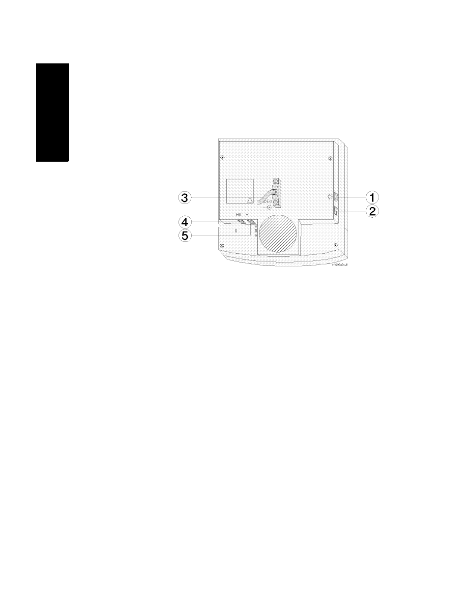
Controls of the
M1095A
Display
1. Brightness Control
2. Standby Switch
Connectors of
the M1095A
Display
3. Combined Video In / Power Connector; a male SCSI
connector with 25 pin pairs is used to input the video
signal and the 60 V dc line voltage.
4. Human Interface Link Connector In; this is a Philips HIL
connector used to connect the handheld keypad.
5. Human Interface Link Connector Out; this is a Philips
HIL connector used to output the information from the
keypad and control panel to the Utility CPU function
card in the computer module.
Note—
The HIL connector cover must be closed when the two HIL
connectors are connected.