Explanation of symbols used, Explanation of symbols used -12 – Philips V24CT User Manual
Page 328
Installation Information
11-12 Monitor Installation and Patient Safety
M
onitor
Ins
ta
lla
ti
on
a
nd Pa
ti
e
n
t Sa
fe
ty
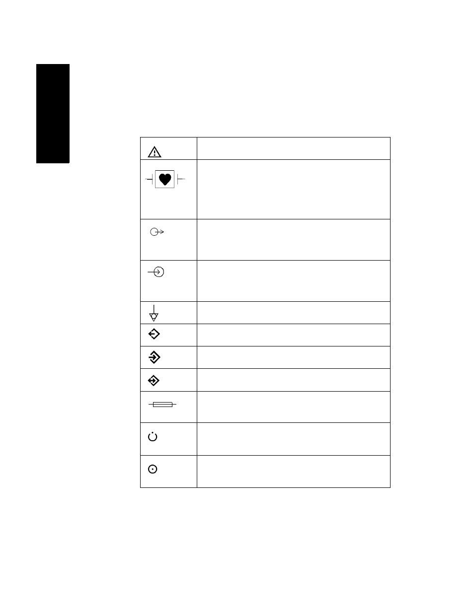
Explanation
of Symbols
used
Attention: Consult accompanying documents.
This symbol appears next to certain connectors
located on the front and/or rear of the instrument. It
indicates that the connectors are designed to have
special protection against electric shocks and are
defibrillator proof.
An electrical output. This symbol is also used to
indicate the gas output on the ssCO
2
module and the
Anesthetic Gas Module.
An electrical input (for example video input) and 60V
dc. This symbol is also used for the gas input to the
Anesthetic Gas Module.
Equipotential grounding system.
Data out
Data in
RS232 input.
Fuse.
Off/Standby.
On.
This manual is related to the following products: