Test 5, 4 issued 3-78 – Generac Power Systems TXP User Manual
Page 25
Attention! The text in this document has been recognized automatically. To view the original document, you can use the "Original mode".
TEST 5 -
STARTED MOTOR
A.) Set VOM to ”+DC" and to a high
enough DC volts scale to permit
reading 12 volts. Connect the POS
ITIVE test probe to starter cable
connection at the starter. Connect
the NEGATIVE (or COMMON) test lead
to ground,then hold Start/Stop
Switch at START. Starter should
run and meter should read 12 Volts.
RESULTS: 1.) Meter, indicates .12.. Volts,
■ but starter does not run...... Replace starter
2.) Starter runs........................................................Continue tests in "Diagnostic
Flow Charts", Section 3
RESULTS: 1.) Starter motor can be heard
running without load,
L ' O O C A O O O O O
.Continue checks in Paragraph
I f R t t
'B
2.) Starter runs and cranks the
engine........................................................Continue tests in. "Diagnostic
Flow Charts", Section 3
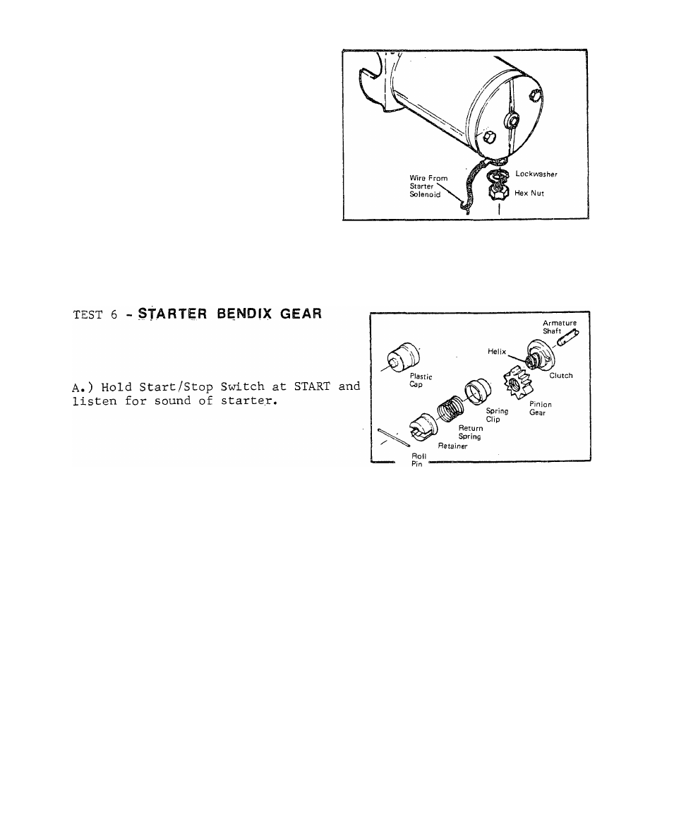
B. ) Remove starter. Inspect pinion gear for damage or excessive wear,
RESULTS: 1.) Starter pinion gear damaged,..................................................Replace
2.) Starter Pinion gear is good,.................................................Continue test (Para
graph C)
C. ) Without installing starter, connect starter cable from starter sol
enoid to starter terminal post. Hold Start/Stop Switch at START. The
starter pinion gear should move outward on the clutch.
4.4
Issued 3-78