5 power manager registers, Power manager registers -22, Table 3-6 – Intel PXA255 User Manual
Page 84
3-22
Intel® PXA255 Processor Developer’s Manual
Clocks and Power Manager
3.5
Power Manager Registers
This section describes the 32-bit registers that control the Power Manager.
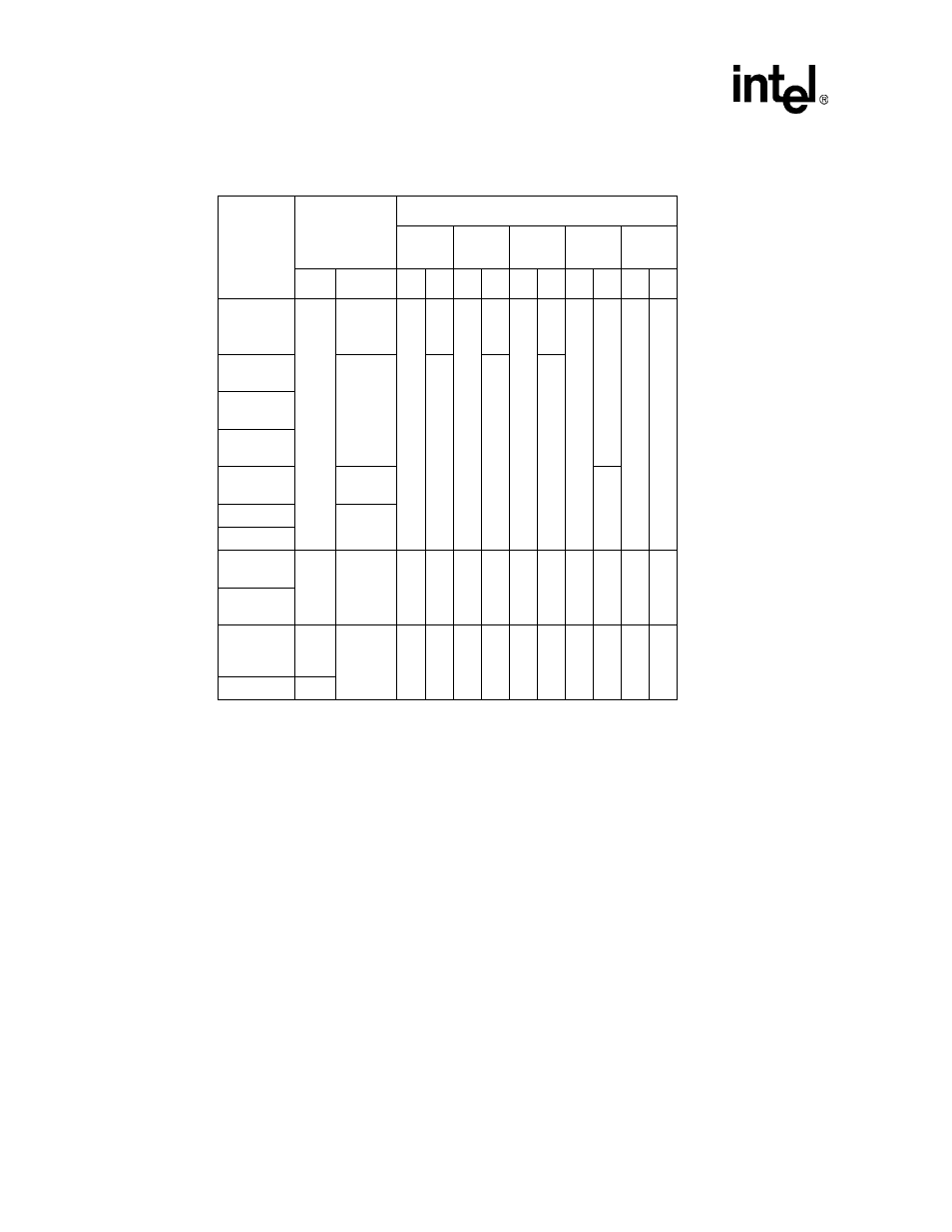
Table 3-6. Power and Clock Supply Sources and States During Power Modes
Module
Supply Source
Power Mode
Turbo
Run
Idle
Freq
Change
Sleep
Pw
Ck
Pw Ck Pw Ck
Pw Ck Pw Ck
Pw Ck
CPU,
Caches,
Buffers
VCC
Run/
Turbo
(R/T)
On
T
On
R
On
Off
On
changi
n
g
Off
Off
Memory
Controller
Mem
On
On
On
LCD
Controller
DMA
Controller
General
Periphs.
PLL
On
OS timer
3.686
MHz Osc
Interrupts
Real Time
Clock
VCC/
Reg
(V/R)
32.768
kHz Osc
V
On
V
On
V
On
V
On
I
On
Power
Manager
GP[3:0], PM
pads, Osc
pads
HV/
Batt
(H/B)
Dynamic/
Static
(D/S)
H
D
H
D
H
D
H
D
H
S
General IO
H
KEY:
T: Turbo clock
R: Run clock
V: Module powered off VCC.
I: Module powered off internal regulator
H: Module powered off VCCQ or VCCN
D: Module is dynamic or actively clocked
S: Module is static or clocks are gated.