Hitachi J300U Series User Manual
Page 47
7-7
7.7
Explanation of Modes
(1) Monitor mode contents
Contents and display
Monitor
mode
contents
FUNC
➤
.
.
.
to
.
to
to
.
FUNC
➤
(1)
(2)
(3)
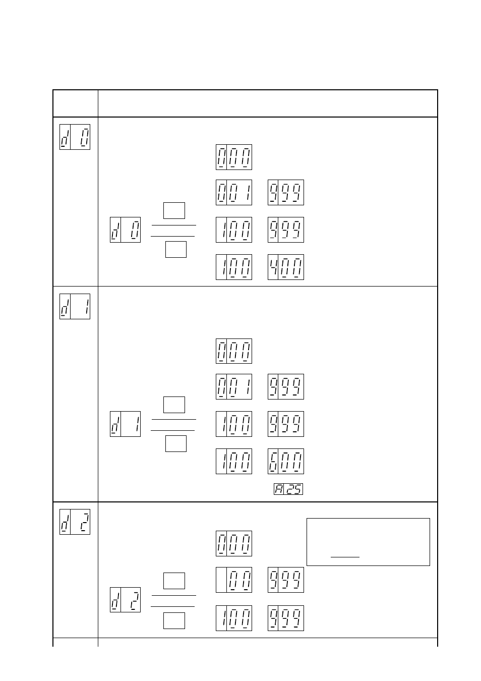
The frequency outputted by the inverter is monitored.
The display is as shown below.
Output
frequency
monitor
Display when stopped
A frequency between 0.01 Hz
and 9.99 Hz is displayed in units
of 0.01 Hz.
A frequency between 10.0 Hz
99.9 Hz is displayed in units
of 0.1 Hz.
A frequency between 100 Hz and
400 Hz is displayed in units of
1 Hz.
FUNC
➤
.
.
.
to
.
to
to
.
FUNC
➤
(1)
(2)
(3)
The rotational frequency converted value of the frequency outputted by the inverter
is displayed.
(Note that the value is not the real rotational frequency of the motor.)
The converted value is displayed as shown below using "rotational frequency/100."
Motor
rotation
speed
monitor
Display when stopped
The converted value is displayed
in units of 0.1 (10 rpm).
From 1000 to 9990 rpm
The converted value is displayed
in units of 1 (100 rpm).
From 10000 to 60000 rpm
The converted value is displayed
in units of 0.01 (1 rpm).
From 1 to 999 rpm
NOTE: Motor pole number can be set by
.
FUNC
➤
.
.
to
to
➤
(2)
The current outputted by the inverter is monitored. The display is as shown below.
Output
current
monitor
Display
when
stopped
A current between 0.1 and 99.9 A
is displayed in units of 0.1 A.
A current between 100 A and 999 A
is displayed in units of 1 A.
.
FUNC
The output display accuracy is about ±10%.
Inverter output current: I
M
Monitor display current: I
MC
Rated current of the inverter: I
R
×
100
≤
±10%
I
MC
- I
M
I
R