Hitachi J300U Series User Manual
Page 31
5-11
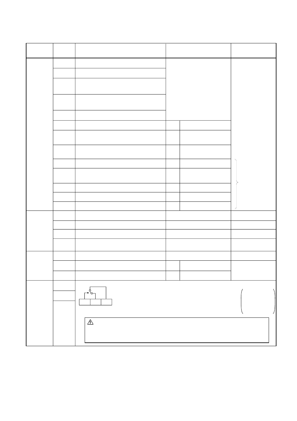
Control circuit
Terminal
symbol
Terminal description and function
FM
CM1
PLC
P24
FW
8
H
OI
L
CM2
11
AL0
AL1
AL2
Remarks
AL1
AL2
Input
monitor
signal
Frequency
command
input
Output
signal
Fault alarm
output
Frequency monitor
Dry contact
Close: ON (run)
Open: OFF (stop)
Min. ON time:
20 ms or more
Common for monitor
Common terminal for the external power
source of the sequencer (PLC)
Internal power source for the frequency
monitor and intelligent input terminal
Forward operation
Intelligent input terminal 8
Power supply for frequency command
Current frequency command
10 VDC
0-5 VDC (nominal), 0-10 VDC
(nominal)(Input impedance 30 k
Ω
)
DC 4-20 mA (nominal)
Input impedance 250
Ω
Common for intelligent output terminal
Run signal
27 VDC
50 mA max
Normal: AL0-AL1 close
Abnormal, Power off:
AL0-AL1 open
Contact rating
250 VAC 2.5 A (Resistor load)
0.2 A (cos¿=0.4)
30 VDC 3.0 A (Resistor load)
0.7 A (cos¿=0.4)
Min 100 VAC
10 mA
5 VDC
100 mA
NOTE1:
Standard setting of
intelligent terminal
Common for frequency command
O
Voltage frequency command
Intelligent output signal 11
12
Intelligent output signal 12
7
Intelligent input terminal 7
6
Intelligent input terminal 6
5
Intelligent input terminal 5
4
Intelligent input terminal 4
3
Intelligent input terminal 3
2
Intelligent input terminal 2
1
Intelligent input terminal 1
REV Reverse operation
CF1 Multistage speed
(First stage)
USP Prevention function of
restart upon power on.
CH1 2 stage acc./dec.
FRS Free run input signal
JG
Jogging
AT
Current input selection
RS
Reset
RUN
Frequency arrival signal
FA1
Note:
If the power is turned
on when the input
terminals 1 to 5 are
kept on, all the data
stored in the inverter
is initialized.
Therefore, never turn
the power on in such
a state.
AL0
Terminal RS can use only contact a (normally open). It cannot use contact b (normally closed).
(NOTE 1)
CAUTION
Alarm connection may contain hazardous live voltage even when inverter is disconnected.
In case of removing flont cover for maintenance or inspection, confirm that incoming power
for alarm connection is surely disconnected.