A-26, 2) function mode – Hitachi J300U Series User Manual
Page 138
A-26
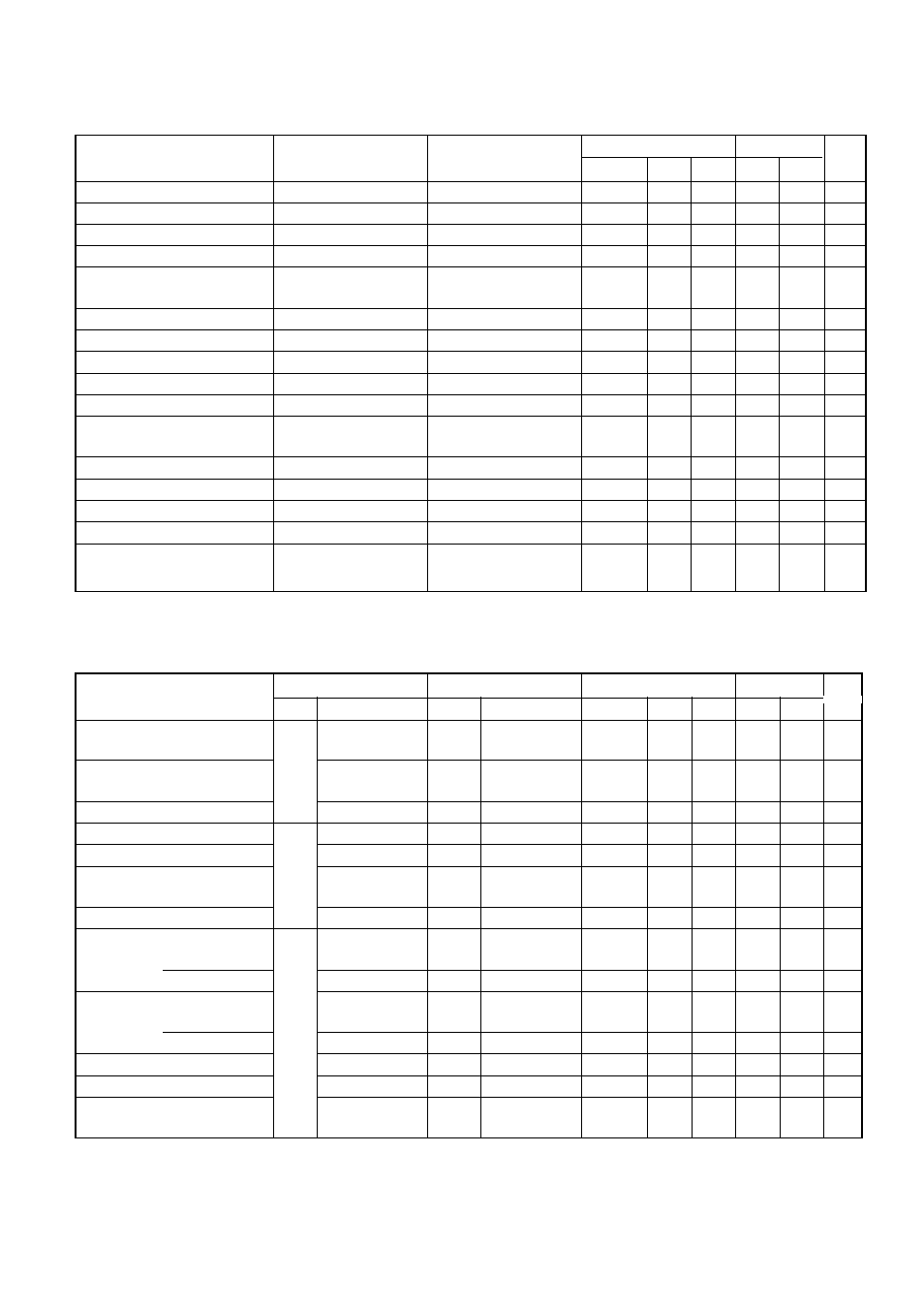
Monitor name
HOP, HRW
DOP, DRW
Alterability
No.
Data
HRW DRW
Trip cause factor 1
ERR1
# ERR1
#
Y
d10
- - -
N
N
Trip frequency 1
ERR1
0.0 Hz ERR1
0.0 Hz
N
—
—
N
N
Trip current 1
ERR1
0.0 A ERR1
0.0 A
Y
d10
- - -
N
N
Trip time P-N voltage 1
ERR1
0.0 Vdc ERR1
0.0 Vdc
Y
d10
- - -
N
N
Integrated count 1 of cause
ERR1 R
0 Y 0 D ERR1 R
0 Y 0 D
N
—
—
N
N
time running days
Integrated error count
ERR COUNT 0
ERR COUNT 0
N
—
—
N
N
Trip cause 2
ERR2
# ERR2
#
Y
d11
- - -
N
N
Trip frequency 2
ERR2
0.0 Hz ERR2
0.0 Hz
N
—
—
N
N
Trip current 2
ERR2
0.0 A ERR2
0.0 A
N
—
—
N
N
Trip time P-N voltage 2
ERR2
0.0 Vdc ERR2
0.0 Vdc
N
—
—
N
N
Integrated count of error
ERR2 R
0 Y 0 D ERR2 R
0 Y 0 D
N
—
—
N
N
time running days
Trip cause 3
ERR3
# ERR3
#
Y
d11
- - -
N
N
Trip frequency 3
ERR3
0.0 Hz ERR3
0.0 Hz
N
—
—
N
N
Trip current 3
ERR3
0.0 A ERR3
0.0 A
N
—
—
N
N
Trip time P-N voltage 3
ERR3
0.0 Vdc ERR3
0.0 Vdc
N
—
—
N
N
Integrated count of error
ERR3 R
0 Y 0 D ERR3 R
0 Y 0 D
N
—
—
N
N
(2) Function mode
Y: Possible
N: Not possible
Display with HOP, HRW Display with DOP, DRW
Function No. with digital operator
Data read/copy
Function mode
Layer
Data display
No.
Data display
Alterability
No.
Data
HRW DRW
Frequency command
1-
1 F-SET
1: REM
Monitor
F-SET-
Y
F9
0
Y
Y
SELECT REM
Operation command
2 F/R
1: REM
Monitor
F/R-SELECT
Y
Y
REM
Parameter selection
3 PARM
0: REM
F-09
PARAM REM
N
—
—
Y
Y
Trip history count clear
2-
1 TCNT
0: CNT
F-38
INITTCNT CNT
N
—
—
Y
Y
Debug mode display selection
2 DEBG
0: OFF
INIT DEBG OFF
N
—
—
N
N
Digital operator rotating direction
3 DOPE
0: FWD
INIT DOPE RWD
Y
F4
F
Y
Y
selection
Reset performance selection
4 RESET 0: ON
INIT RESET ON
Y
F86
0
Y
Y
Base frequency setting
First setting
3-1-1
1 F-BASE 50 Hz
F-00
F-BASE 0050 Hz
Y
A62
50
Y
Y
Second setting
1 F-BASE 50 Hz
F-BASE 0050 Hz
Y
A62
50
Y
N
Max. frequency setting
First setting
2 F-MAX 50 Hz
F-01
F-MAX 0050 Hz
Y
A63
50
Y
Y
Second setting
2 F-MAX 50 Hz
F-MAX 0050 Hz
Y
A63
50
Y
N
Start frequency setting
3 Fmin
0.5 Hz
F-02
Fmin 0.50 Hz
Y
A4
0. 50
Y
N
Motor voltage setting
4 A-AC
0: 200 V
F-03
AVR AC200 V
Y
F11
200
Y
Y
AVR function ON/OFF during
5 A-DEC 0: ON
AVR DEC ON
N
—
—
Y
Y
deceleration
set
value
set
value
Display with
Display with
Function No. with digital operator
Data read/copy