Relay rack frame grounding requirements, External alarm, reference, and control wire sizes – Emerson SAG581126000 User Manual
Page 90
SAG581126000
System Application Guide
Issue AD, November 23, 2009
Spec. No. 581126000 (Model 700
NVBA
)
Page 90 of 123
This document is property of Emerson Network Power, Energy Systems, North America, Inc. and contains confidential and proprietary information owned by Emerson Network Power, Energy
Systems, North America, Inc. Any copying, use, or disclosure of it without the written permission of Emerson Network Power, Energy Systems, North America, Inc. is strictly prohibited.
AC Input Branch Circuit Protection and Wire Size Selection
Refer to PD588705100/PD588705101/PD588705102/PD588705103/PD588705104.
Relay Rack Frame Grounding Requirements
Ordering Notes
1) For relay rack grounding requirements, refer to the current edition of the American National Standards
Institute (ANSI) approved National Fire Protection Association's (NPFA) National Electrical Code (NEC),
applicable local codes, and your specific site requirements.
A customer's grounding network lead can be attached to the top of each relay rack. Provision is made for
installing a lead with a two-hole lug that has 1/4" bolt clearance holes on 5/8" centers. Refer to Table
for lug selection.
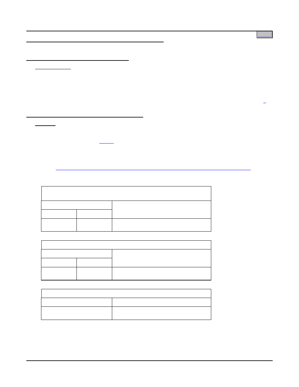
External Alarm, Reference, and Control Wire Sizes
Features
♦ External alarm, reference, and control connection points are located on…
• J1-J4 on the optional
Audible Alarm and Alarm Termination Circuit Card P/N 509539,
• TB1 on circuit card P/N 509532, and
• J8 on circuit card P/N 534868 (if List 71 not installed).
♦ See
“
Electrical Connections Locations and Dimensions; External Alarm, Reference, and Control
” under
PHYSICAL SIZE INFORMATION for illustration.
J1-J4 on Optional List 71 Audible Alarm and
Alarm Termination Circuit Card P/N 509539
Terminals
Capacity Type
Recm
Wire Size
26 to 16
AWG
Spring-Clamp
22 AWG for Loop Lengths Up to 200 ft.
18-20 AWG for Loop Lengths Over 200 ft.
TB1 on Circuit Card P/N 509532
Terminals
Capacity Type
Recm
Wire Size
26 to 16
AWG
Spring-Clamp
22 AWG for Loop Lengths Up to 200 ft.
18-20 AWG for Loop Lengths Over 200 ft.
J8 on Circuit Card P/N 534868
Terminals
Recm Wire Size
D-Type Connector
22 AWG for Loop Lengths Up to 200 ft.
18-20 AWG for Loop Lengths Over 200 ft.