Field expansion kit (one [1] 8-position, Module mounting assembly) – Emerson SAG581126000 User Manual
Page 24
SAG581126000
System Application Guide
Issue AD, November 23, 2009
Spec. No. 581126000 (Model 700
NVBA
)
Page 24 of 123
This document is property of Emerson Network Power, Energy Systems, North America, Inc. and contains confidential and proprietary information owned by Emerson Network Power, Energy
Systems, North America, Inc. Any copying, use, or disclosure of it without the written permission of Emerson Network Power, Energy Systems, North America, Inc. is strictly prohibited.
6) Order a Module Mounting Position Blank Cover Panel,
, for each empty module
mounting position in the system.
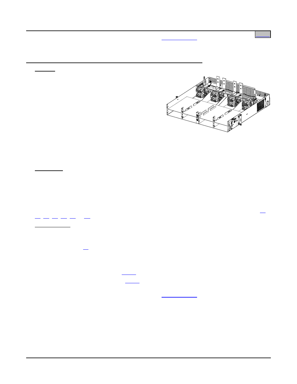
List 31: Field Expansion Kit: One (1) 8-Position Module Mounting Assembly
Features
♦ Provides one (1) Spec No. 588705100 Module
Mounting Assembly and components required for field
installation in an existing Power System that has eight
(8) to twenty-four (24) positions.
♦ Included are busbars for connecting rectifier output to
the main system bus, and cables for connecting
DC-DC Converter output to the appropriate dual
voltage bus distribution panel assembly (if using
converters).
♦ The Module Mounting Shelf provides eight (8)
mounting positions for Rectifier Modules (PCUs). When the shelf is equipped with a DC-DC Converter
Option Kit, the four (4) middle positions will accept either Rectifier Modules (PCUs) or +24V/-48V DC-DC
Converter Modules. Note that Supplemental Bays CANNOT have Converter Modules.
♦ Refer to Power Data Sheet PD588705100 for more information.
Restrictions
For field installation only.
Maximum number of List 31 that can be installed in a power bay is one (1).
Original system must have a Module Mounting Assembly (up to twenty-four [24] positions).
Cannot be used in a power bay equipped with a Spec No. 588705104 Module Mounting Assembly.
Converter Modules must be used in conjunction with a dual voltage bus distribution panel assembly (List
,
,
). Note that Supplemental Bays CANNOT have Converter Modules.
Ordering Notes
1) For a bay equipped with Spec. No. 588705101 List 1, Spec. No. 588705102 List 1, or Spec. No.
588705103 List 1, order one (1) List 31.
2) Order one (1) List
(DC-DC Converter Option Kit) for each List 31 requiring DC-DC Converters. The kit
permits the middle four (4) positions in the 8-position Module Mounting Shelf to accept DC-DC Converter
Modules or Rectifier Modules (PCUs). List 60 is factory installed within the 8-position Module Mounting
Shelf in the assembly. Note that Supplemental Bays CANNOT have Converter Modules.
3) Order Rectifier Modules (PCUs) per
as required.
4) Order DC-DC Converter Modules per
as required.
Note that Supplemental Bays CANNOT have Converter Modules.
5) Order a Module Mounting Position Blank Cover Panel,
, for each empty module mounting
position in the assembly.