Emerson SAG581126000 User Manual
Page 4
SAG581126000
System Application Guide
Issue AD, November 23, 2009
Spec. No. 581126000 (Model 700
NVBA
)
Page 4 of 123
This document is property of Emerson Network Power, Energy Systems, North America, Inc. and contains confidential and proprietary information owned by Emerson Network Power, Energy
Systems, North America, Inc. Any copying, use, or disclosure of it without the written permission of Emerson Network Power, Energy Systems, North America, Inc. is strictly prohibited.
581126000
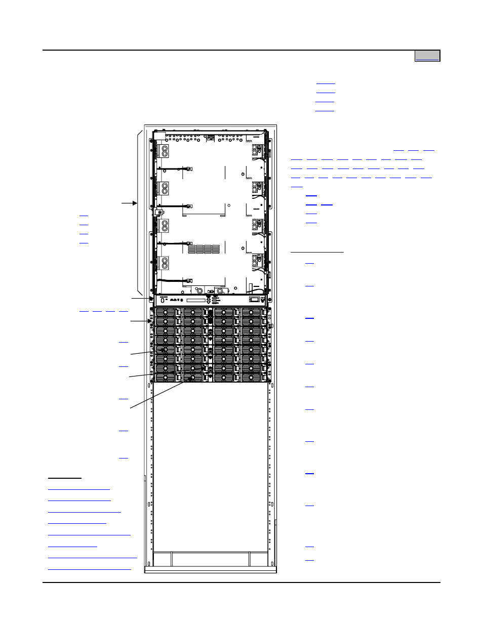
Distribution Bus
Row A (Row 1)
Distribution Bus
Row B (Row 2)
Distribution Bus
Row C (Row 3)
Distribution Bus
Row D (Row 4)
Distribution Cabinet
List
(4-Row)
List
(3-Row)
List
(2-Row)
List
(1-Row)
Module Mounting
Assembly Interface
,
,
,
,
,
,
,
,
,
,
,
,
,
,
List
: LV Battery Disconnect
List
: Manual Battery Disconnect
List
: LV/Manual Battery Disconnect
List
: LV Battery Disconnect
MCA
Other Options
List
: Distribution Cabinet Top
Shield
List
: Field Expansion Kit: One
(1) 8-Position Module Mounting
Assembly
List
: Optional Audible Alarm and
Alarm Termination Circuit Card
List
: MCA Interface Modem
Option
List
: MCA Interface WinLink
Software
List
: MCA Interface Combination
Modem/RS-232 Option
List
: MCA Interface Ethernet
Option: WinLink Compatible + Web
Interface
List
: MCA Interface Ethernet
Option: WinLink Compatible + Web
Interface + SNMP
List
: MCA Interface Ethernet
Option: WinLink Compatible + Web
Interface + Battery Monitoring
List
: MCA Interface Ethernet
Option: WinLink Compatible + Web
Interface + SNMP + Battery
Monitoring
List
: Battery Stand System
List
: Battery Tray
Rectifier Module
Optional DC-DC
Converter Module
or
Rectifier Module
See Also
DC-DC Converter Option
Interface Component Kit
Main Bay:……………………………………………...…
Supplemental Bay (located next to Main Bay):………
Supplemental Bay 'Distribution Only' Option:………..
Supplemental Bay (located away from Main Bay):….