Gj/218-type circuit breakers – Emerson SAG581126000 User Manual
Page 76
SAG581126000
System Application Guide
Issue AD, November 23, 2009
Spec. No. 581126000 (Model 700
NVBA
)
Page 76 of 123
This document is property of Emerson Network Power, Energy Systems, North America, Inc. and contains confidential and proprietary information owned by Emerson Network Power, Energy
Systems, North America, Inc. Any copying, use, or disclosure of it without the written permission of Emerson Network Power, Energy Systems, North America, Inc. is strictly prohibited.
GJ/218-Type Circuit Breakers
Restrictions
A bus arrangement must be specified that contains GJ/218-type circuit breaker positions.
Load should not exceed 80% of device rating.
for required distribution row mounting positions.
Ordering Notes
1) Order circuit breakers as required per
Table 5 (GJ/218 Circuit Breakers)
2) Order a jumper kit as required for each circuit breaker per
.
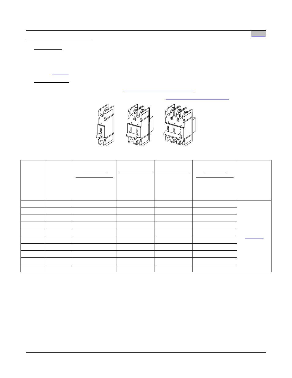
GJ/218 Circuit Breakers
Ampere
Rating
Number
of
Positions
P/N
Electrical/
Mechanical Trip
1
without
Internal Shunt
P/N
Electrical Trip
2
without
Internal Shunt
P/N
Electrical Trip
2
with
Internal Shunt
(25mV @ full
rated load)
3
P/N
Electrical/
Mechanical Trip
1
with
Internal Shunt
(25mV @ full
rated load)
3
for wire size
and lug
selection,
refer to the
following
table
100 1 256621700
256621300
516184
123580
125 1 256621600
256621400
516187
123631
150 1 256621800
256622400
516185
123632
175 1 256621900
256622500
516186
123633
200 1 256622200
256622600
516188
123634
225 1 256622900
256622700
516189
123635
250 1 256623500
256623400
516190
123636
300 2 256625300 103572
--
--
400 2 256626200
256626300 --
--
600 3 256628200 103571
--
--
1, 2
Circuit Breaker Alarm Operation:
1
Provides an alarm during an electrical or manual trip condition.
2
Provides an alarm during an electrical trip condition only.
3
Extended shunt leads are 22 AWG stranded wire, approximately 7-10 ft. long from exit point at bottom of
Distribution Cabinet. Each shunt lead is equipped with a 49.9 ohm current limiting resistor.
Table 5
GJ/218 Circuit Breakers