List 29: top shield for distribution cabinet, Distribution cabinet top shield, Module mounting – Emerson SAG581126000 User Manual
Page 23: Assembly interface components, List
System Application Guide
SAG581126000
Spec. No. 581126000 (Model 700
NVBA
)
Issue AD, November 23, 2009
Page 23 of 123
This document is property of Emerson Network Power, Energy Systems, North America, Inc. and contains confidential and proprietary information owned by Emerson Network Power, Energy
Systems, North America, Inc. Any copying, use, or disclosure of it without the written permission of Emerson Network Power, Energy Systems, North America, Inc. is strictly prohibited.
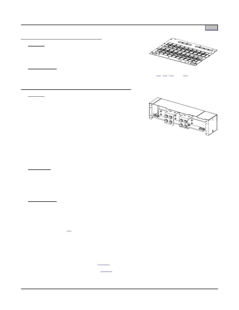
List 29: Top Shield for Distribution Cabinet
Features
♦ Plastic shield covers all wiring access openings in top of
Distribution Cabinet. Individual cutouts can be removed for
wiring as required for specific installation.
Ordering Notes
1) Where closed top cover is required, order one (1) List 29 for each List
,
,
ordered.
List 30: Module Mounting Assembly Interface Components
Features
♦ Provides components to add one (1) Module Mounting
Assembly (Spec. No. 588705101, 588705102, 588705103, or
588705104) to a Main or Supplemental Bay.
♦ The separately ordered Module Mounting Assembly can
consist of one (1), two (2), three (3), or four (4) factory
interconnected 8-position Module Mounting Shelves. Each
Module Mounting Shelf in a Module Mounting Assembly
provides eight (8) mounting positions for Rectifier Modules
(PCUs). When the Module Mounting Shelf is equipped with a DC-DC Converter Option Kit, the four (4)
middle positions will accept either Rectifier Modules (PCUs) or +24V/-48V DC-DC Converter Modules.
Note that Supplemental Bays CANNOT have Converter Modules.
♦ Refer to Power Data Sheet PD588705100/PD588705101/PD588705102/PD588705103/PD588705104 for
Module Mounting Assembly information.
Restrictions
Factory installed only on the Distribution Cabinet.
Includes 'Module Mounting Assembly-to-Power System/Distribution Cabinet' interconnect components only.
The Module Mounting Assembly must be ordered separately.
Each bay can be equipped with a maximum of one (1) Module Mounting Assembly.
Ordering Notes
1) Order one (1) List 30 per bay, regardless of the number of module mounting positions required (32
positions maximum per bay).
2) Order a Module Mounting Assembly per Power Data Sheet
PD588705101/PD588705102/PD588705103/PD588705104 as required.
3) Order one (1) List
(DC-DC Converter Option Kit) for each 8-position Module Mounting Shelf in which
DC-DC Converters are required. Note that some Module Mounting Assemblies consist of multiple
8-position Module Mounting Shelves. The kit permits the middle four (4) positions in an 8-position Module
Mounting Shelf to accept DC-DC Converter Modules or Rectifier Modules (PCUs). List 60 is factory
installed within the 8-position Module Mounting Shelf. List 60 kits will be installed starting with bottom
8-position Module Mounting Shelf in the Module Mounting Assembly and working up. Note that
Supplemental Bays CANNOT have Converter Modules.
4) Order Rectifier Modules (PCUs) per
as required.
5) Order DC-DC Converter Modules per
as required.
Note that Supplemental Bays CANNOT have Converter Modules.