Rear panel view, Sd rear panel view, Chapter 1 product description – Grass Valley K2 Media Client System Guide Oct.10 2006 User Manual
Page 30
30
K2 Media Client System Guide
September 7, 2006
Chapter 1 Product Description
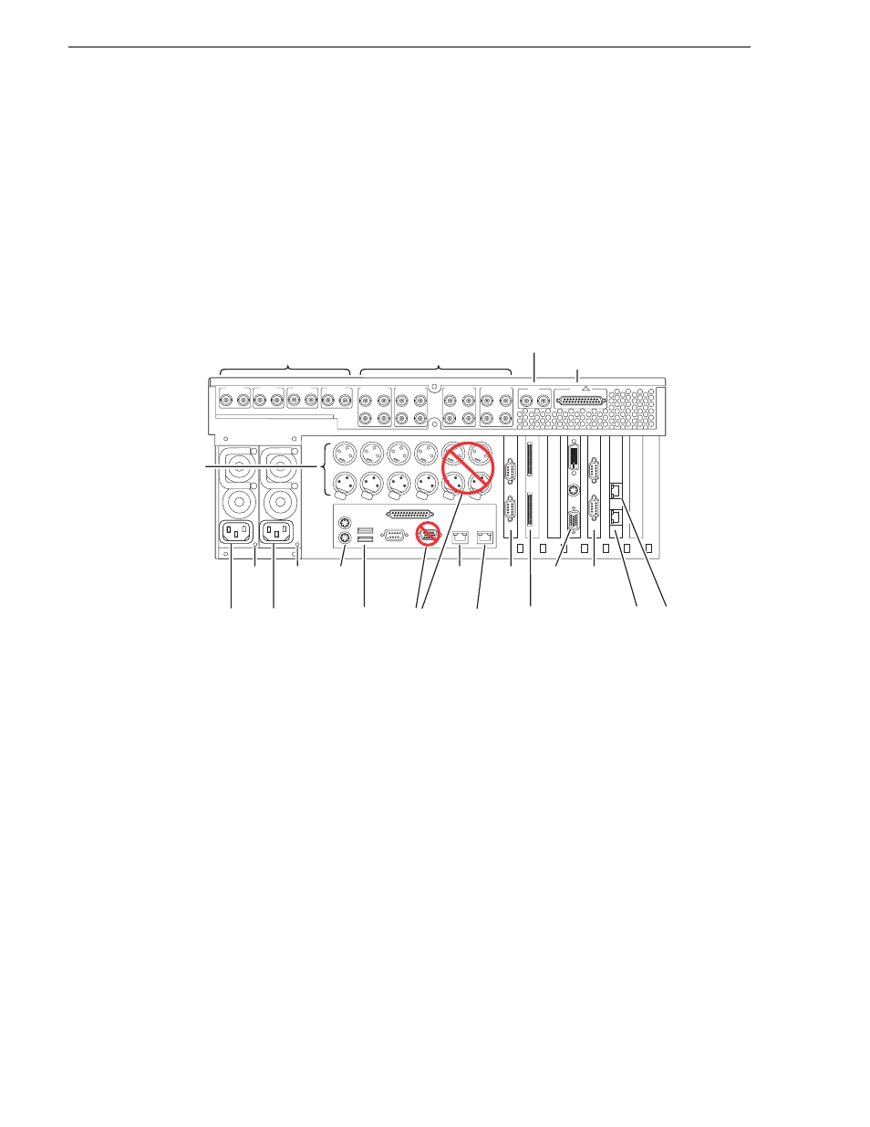
Rear panel view
The following drawings identify the rear panel connectors and components. The cards
are in different locations for the SD and HD/SD rear panels.
NOTE: In both the SD and HD/SD models, the GigE port 3/port 4 board can be
replaced by an FC board (optional).
SD rear panel view
Pu
sh
Pu
sh
Pu
sh
Pu
sh
Pu
sh
Pu
sh
GPIO
!
SDI CH 1
IN
OUT
SDI CH 2
IN
OUT
SDI CH 3
IN
OUT
SDI CH 4
IN
OUT
AES/EBU CH 1
IN
OUT
1-2
3-4
1-2
3-4
1-2
3-4
1-2
3-4
1-2
3-4
1-2
3-4
1-2
3-4
1-2
3-4
AES/EBU CH 2
IN
OUT
AES/EBU CH 3
IN
OUT
AES/EBU CH 4
IN
OUT
OUT
OUT
OUT
OUT
IN
LTC CH 1
LTC CH 2
LTC CH 3
LTC CH 4
UNUSED
UNUSED
IN
IN
IN
REF
COMPOSITE LOOP
THRU
Video In/Out
(Loop-Thru)
Audio In/Out
Reference
In
GPI
Power
Good
LED
Power
Good
LED
Keyboard
/Mouse
USB
VGA
Display
GigE
Port 1
RS-422
RS-422
Do Not
Use
Do Not
Use
GigE
Port 4
GigE
Port 3
GigE
Port 2
Power
Cord
LTC
In/Out,
Per
Channel
Power
Cord