Epson – Epson Power Supply S1F70000 User Manual
Page 87
S1F76640 Series
2–44
EPSON
S1F70000 Series
Technical Manual
Note 1 :
At the 3 times step-up time, 2 times step-up output (–10V) cannot be taken out from the CAP2– pin.
Note 2 :
At the 4 times step-up time, 2 times step-up output (–10V) cannot be taken out from the CAP2– pin.
Note 3 :
At the 4 times step-up time, 3 times step-up output (–15V) cannot be taken out from the CAP3– pin.
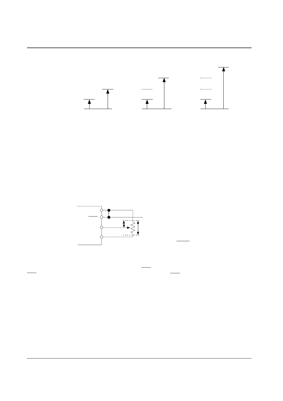
Reference Voltage Generator, Voltage Stabilization Circuit
The reference voltage generator generates reference voltage necessary for operation of the voltage stabilization
circuit and adds temperature gradient to reference voltage. Three temperature gradients are available, and signal
from the temperature gradient selection circuit select one of them.
The voltage stabilization circuit stabilizes the step-up output voltage V
O
and outputs optional voltages. When
an external resistor R
RV
is connected as shown in Figure 5-5 and the potential of the intermediate tap is changed,
V
REG
output voltage can be set to optional voltages between the reference voltage V
RV
and V
O
.
Figure 5-6 Voltage Stabilization Circuit
The voltage stabilization circuit has power off function and can control ON/OFF of V
REG
output according to
signals from the system side (microprocessor, etc.) When P
OFF
is high (V
DD
), V
REG
output is turned on, and when
P
OFF
is Low (GND), it is turned off. When the control is not necessary, P
OFF
is fixed to High (V
DD
).
CAP1+=2V
DD
=10V
V
DD
=5V
GND=0V
V
DD
=5V
GND=0V
V
DD
=5V
GND=0V
CAP2+=3V
DD
=15V
Note 1
Note 3
Note 2
CAP3+=4V
DD
=20V
Figure 5-3
Example of 2 times step-up
potential relations
Figure 5-4
Example of 3 times step-up
potential relations
Figure 5-5
Example of 4 times step-up
potential relations
V
SS
P
OFF
RV
V
REG
R
1
R
RV
=100k
Ω
to 1M
Ω
Control signal
V
REG
=
R
RV
R
1
· V
RV