Epson – Epson Power Supply S1F70000 User Manual
Page 144
S1F79100Y Series
S1F70000 Series
EPSON
3–37
Technical Manual
S1F79100Y
Series
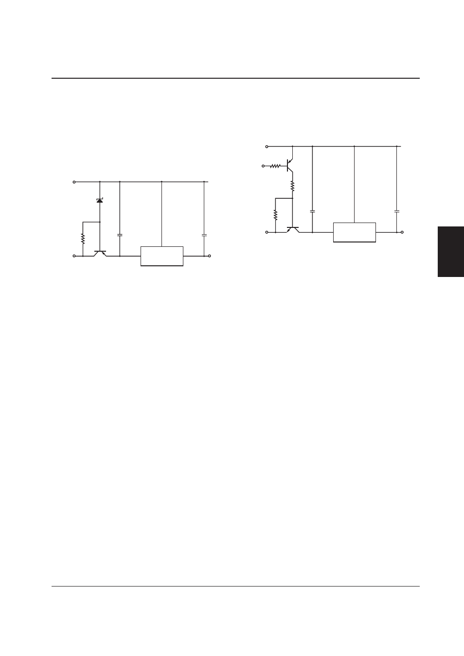
R
1
helps reduce the affect of I
SS
on V
F
. It is also re-
quired when I
SS
is lower than the diode bias current.
For certain input voltages, a Zener diode with the re-
verse polarity can be used.
High Input Voltages
A preliminary regulator circuit is required to bring the
input voltage within the S1F79100Y series rated range.
GND
V
O
V
I
V
O
V
I
V
SS
S1F79100Y
Switching Output
S1F79100Y series devices are designed for continuous
operation. An external switching circuit allows the
regulated output to be switched ON and OFF.
GND
ON/OFF
control signal
V
O
V
I
V
O
V
I
V
SS
S1F79100Y
Note) Temperatures during reflow soldering must re-
main within the limits set out under LSI Device
Precautions in this catalog. Do not immerse
QFP and SOT89 packages during soldering, as
the rapid temperature gradient during dipping
can cause damage.