Epson, Parallel connection (for increased boosting) – Epson Power Supply S1F70000 User Manual
Page 75
S1F76540 Series
2–32
EPSON
S1F70000 Series
Technical Manual
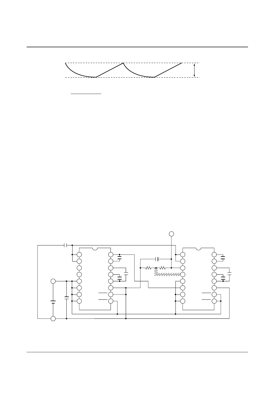
Parallel Connection (for Increased Boosting)
The parallel connection is useful for reduction of
booster output impedance or reduction of ripple volt-
age. In the parallel connection of “n” lines, the booster
output impedance can be reduced to approximately “1/
n". Only the smoothing capacitor (C
O
) for booster out-
put can be used commonly in the parallel connection.
When using the regulator, use only one of “n”
S1F76540 chips which are in parallel connection. (If
multiple regulators are operated in parallel mode, the
reactive current consumption occurs.) Figure 2.11
gives a wiring example of 4-time booster and regulator
where two S1F76540s are parallelly connected.
V
RP
=
I
O
+ I
O
• R
COUT
• • • • Equation (4)
2 • f
CL
• C
O
where,
I
O
: Load current (A)
f
CL
: Clock frequency (Hz)
R
COUT
: Serial equivalent resistance (
Ω
) of output capacitor C
O
Figure 2.10 Ripple waveforms
◊
Application in other setup conditions
1 When used in the High Output mode
Connect the FC pin to the V
I
pin.
Figure 2.11 Parallel connection example
V
RP
+
C2
+
+
C3
C1
1
2
3
4
5
6
7
8
V
O
V
RI
V
REG
RV
V
DD
FC
TC1
TC2
C2P
C2N
C3N
C1N
C1P
V
I
P
OFF1
P
OFF2
16
15
14
13
12
11
10
9
+
C2
+
R2
C
REG
V
REG
R1
+
+
C3
C
O
V
DD
V
I
C
I
C1
1
2
3
4
5
6
7
8
V
O
V
RI
V
REG
RV
V
DD
FC
TC1
TC2
C2P
C2N
C3N
C1N
C1P
V
I
P
OFF1
P
OFF2
16
15
14
13
12
11
10
9
+
+