Application circuit examples, Epson, Four-time booster and regulator – Epson Power Supply S1F70000 User Manual
Page 73
S1F76540 Series
2–30
EPSON
S1F70000 Series
Technical Manual
APPLICATION CIRCUIT EXAMPLES
Four-time Booster and Regulator
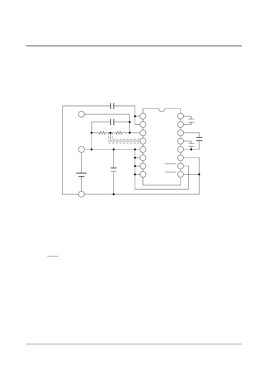
Figure 2.8 gives a wiring example of four-time booster
and regulator that is the typical S1F76540 application.
This example boosts the input voltage (V
I
) four times in
negative direction, and outputs the regulated voltage at
V
REG
pin.
◊
Setup conditions of Figure 2.8
• Internal clock : ON (Low Output mode)
• Booster circuit : ON
• Regulator
: ON (if C
T
= –0.04%/
°
C)
◊
Power-off procedure
• Set the P
OFF1
pin to logical low (V
I
) to turn off all circuits.
◊
Regulator
• For the regulator setup and notes, see the “voltage regulator circuit” section.
◊
Application in other setup conditions
1 When used in the High Output mode
• Connect the FC pin to the V
I
pin.
2 When changing the temperature coefficient (C
T
)
• Change the TC1 and TC2 pin setup by following the definition of Table 2.7.
R1
V
O
V
RI
V
REG
RV
V
DD
FC
TC1
TC2
C2P
C2N
C3N
C1N
C1P
V
I
P
OFF1
P
OFF2
R2
C2
C1
C3
1
2
3
4
5
6
7
8
C
I
V
I
V
DD
V
REG
C
O
C
REG
+
+
+
+
16
15
14
13
12
11
10
9
+
+
Figure 2.8 Wiring example of 4-time booster and regulator