Epson, Parallel connection, Series connection – Epson Power Supply S1F70000 User Manual
Page 101
S1F76640 Series
2–58
EPSON
S1F70000 Series
Technical Manual
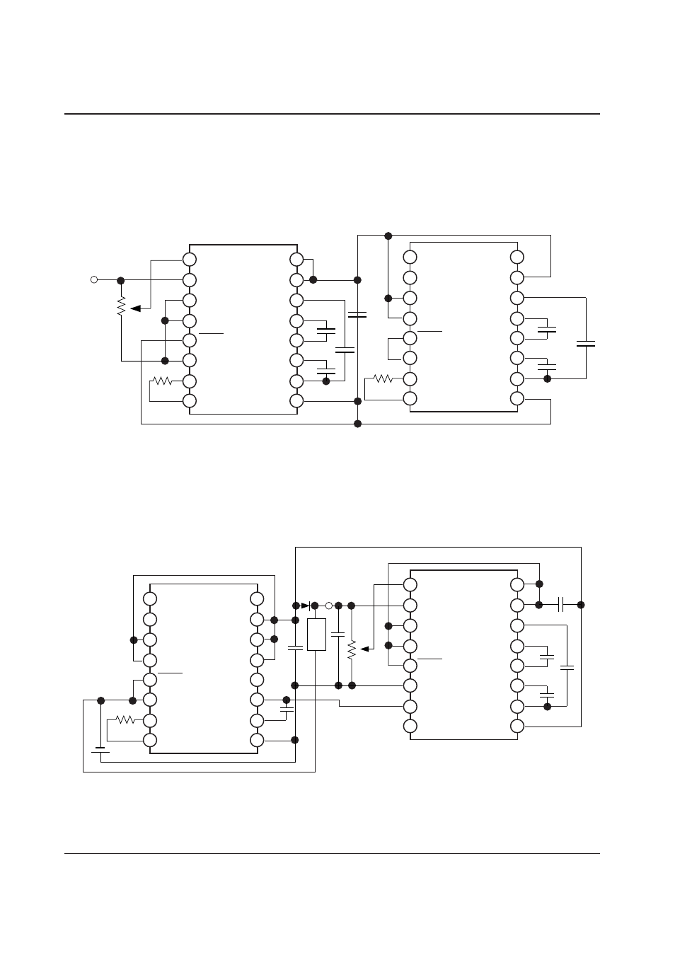
Parallel Connection
It is possible to make the output impedance R
O
small when several pieces of the circuit shown in Figure 8.1 are
connected. Parallel connection of n circuits reduces R
O
to 1/n approximately. One piece of the smoothing capaci-
tor C
4
can be commonly used in the same way. To get stabilized outputs after parallel connection, include 1 pieces
of the circuit shown in Figure 8.2 in the parallel connection of n circuits as shown in Figure 8.3.
Figure 8.3 Parallel Connection
Series Connection
When S1F76640 is connected in series (V
DD
and V
O
in the previous stage are connected to GND and V
DD
in the
next stage respectively), the output voltage can be increased more. But the series connection makes the output
impedance high. Figure 8.4 shows an example of the series connection to get V
O
=25V from V
DD
=5V and to
stabilize it.
Figure 8.4 Series Connection
RV
V
REG
TC1
TC2
P
OFF
V
SS
OSC1
OSC2
1
2
3
4
5
6
7
8
16
15
14
13
12
11
10
9
V
RI
V
O
CAP3+
CAP2+
CAP2–
CAP1+
CAP1–
V
DD
RV
V
REG
TC1
TC2
P
OFF
V
SS
OSC1
OSC2
1
2
3
4
5
6
7
8
16
15
14
13
12
11
10
9
V
RI
V
O
CAP3+
CAP2+
CAP2–
CAP1+
CAP1–
V
DD
C
3
C
2
C
2
C
1
C
1
C
4
C
3
+
–
+
–
+
–
+
–
+
–
+
–
+
–
V
REG
R
RV
(100k
Ω
=1M
Ω
)
+
–
+
–
+
–
+ –
+
–
+
–
RV
V
REG
TC1
TC2
P
OFF
V
SS
OSC1
OSC2
1
2
3
4
5
6
7
8
16
15
14
13
12
11
10
9
V
RI
V
O
CAP3+
CAP2+
CAP2–
CAP1+
CAP1–
V
DD
RV
V
REG
TC1
TC2
P
OFF
V
SS
OSC1
OSC2
1
2
3
4
5
6
7
8
16
15
14
13
12
11
10
9
V
RI
V
O
CAP3+
CAP2+
CAP2–
CAP1+
CAP1–
V
DD
C
1
D
1
Load