Epson Power Supply S1F70000 User Manual
Page 176
S1F76300 Series
S1F70000 Series
EPSON
4–31
Technical Manual
S1F76300
Series
Parameter
Symbol
Conditions
Rating
Unit
Min. Typ. Max.
Forward voltage
V
F
I
F
= 1.1A,
—
—
0.55
V
pulse measurement
Reverse current
I
R
V
R
= V
RM
,
—
—
1
mA
pulse measurement
Junction-to-lead thermal resistance
θ
jl
—
—
23
˚C/W
Junction-to-ambient thermal resistance
θ
ja
—
—
157
˚C/W
Package
Static capacitance
Tan
δ
Leakage
Device
type
Voltage (V)
(
µ
F)
+25, +85
+125
–55
current (
µ
A)
˚C
˚C
˚C
MSVA0J475M
A
6.3
4.7
0.08
0.1
0.12
0.5
MSVB20J106M
B2
6.3
10
0.08
0.1
0.12
0.6
MSVB20J156M
B2
6.3
15
0.08
0.1
0.12
0.9
MSVB0J156M
B
6.3
15
0.08
0.1
0.12
0.9
MSVC0J336M
C
6.3
33
0.08
0.1
0.12
2.0
MSVD20J686M
D2
6.3
68
0.08
0.1
0.12
4.2
MSVD0J686M
D
6.3
68
0.08
0.1
0.12
4.2
Note
The figures on the previous pages show data from the documents of various manufacturers. For further details,
please contact the relevant manufacturer.
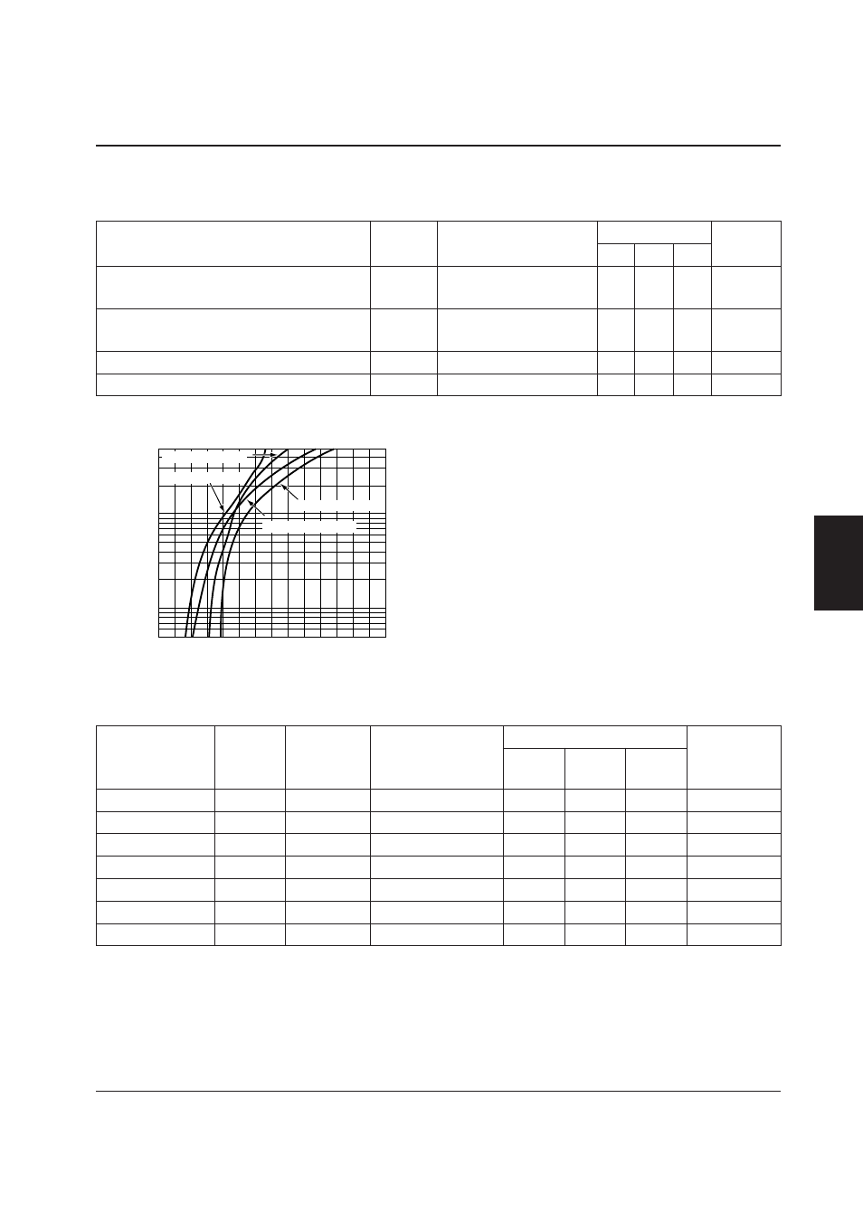
Diodes
Shindengen DINS4 Schottky barrier diodes
Characteristics
Smoothing capacitors
NEC MSV series capacitors
1.4
0.8
0.6
Forward voltage (V)
F
orw
ard current (A)
0.4
0.2
0
5
2
1
0.5
0.2
0.1
0.05
1.0
1.2
Tp = 25 ˚C (Max.)
Tp = 125 ˚C (Max.)
Tp = 125 ˚C (Typ.)
Tp = 25 ˚C (Typ.)