Parallel connector, 2 − names and functions of parts – Teac HS-2000 User Manual
Page 14
14
TASCAM HS-2000
2 − Names and functions of parts
@
GROUND terminal
When using a TASCAM RC-HS32PD or RC-HS20PD
remote control (sold separately), depending on the
operating environment, the color display might flicker
or noise might be heard when monitoring. If this
occurs, use the GROUND terminal to ground the unit.
(No wire is provided for this use, so please prepare
your own.)
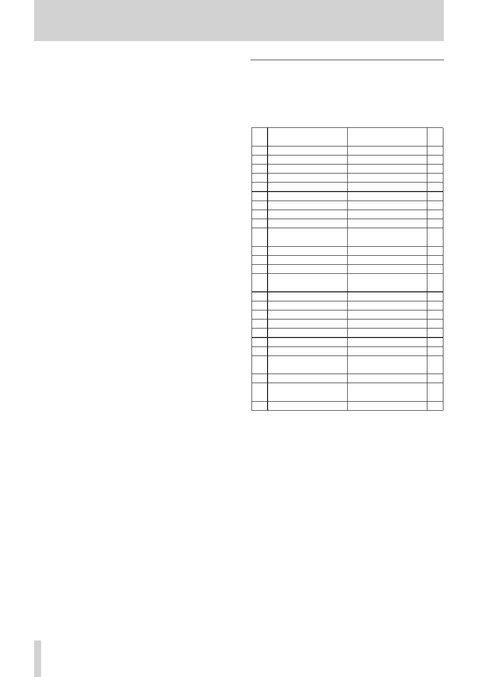
PARALLEL connector
The PARALLEL connector on the rear panel allows
external control of this unit.
You can also connect a TASCAM RC-SS20. (Connect to the
RC-SS20’s REMOTE 1 connector.)
The pin assignments are as follows.
Pin
No.
Normal
TASCAM RC-SS20
PonMode
I/O
1 GND
GND
2 PLAY
FLASH 1
I
3 STOP
FLASH 2
I
4 RECORD
FLASH 3
I
5 SKIP FWD
FLASH 4
I
6 SKIP BWD
FLASH 5
I
7 (Reserved)
STOP
I
8 FADER_START
FADER_START
I
9 TALLY_BC_STOP
TALLY_BC_STOP
O
10 TALLY_PAUSE/TALLY_BC_
PAUSE
TALLY_PAUSE/TALLY_BC_
PAUSE
O
11 TALLY_RECORD
RESERVED
O
12 TALLY_STOP
TALLY_STOP
O
13 TALLY_PLAY
TALLY_PLAY
O
14 REMOTE_SELECT,
H or Open
REMOTE_SELECT, L
I
15 PAUSE
FLASH 6
I
16 (Reserved)
FLASH 7
I
17 AUX1, FF
FLASH 8
I
18 AUX2, REW
FLASH 9
I
19 AUX3, MARK
FLASH 10
I
20 (Reserved)
FLASH_PAGE
I
21 TALLY_BC_STANDBY
TALLY_BC_STANDBY
O
22 TALLY_CF1/TALLY_BC_
CM
TALLY_CF1/TALLY_BC_
CM*
O
23 TALLY_ONLINE
TALLY_ONLINE
O
24 TALLY_CF2/TALLY_BC_
END
TALLY_CF2/TALLY_BC_
END**
O
25
+5V***
+5V***
I: Command input for transport control
Internal circuit, +5V pull-up
Operates with low commands of 50 msec or more
O: Command output, for tally output
The internal circuit is open collector (10Ω output impedance)
Outputs low commands when operating
20V maximum voltage, 35mA maximum current
*With an RC-SS20, assigned to the CF indicator
**With an RC-SS20, assigned to the CD indicator
***+5V: 50mA maximum supplied current