Super Systems PC Configurator 2 User Manual
Page 163
Super Systems Inc.
Page 163 of 201
Configurator Manual #4562 Rev D
The values in the first (top) list box are:
PV 1 Value
PV 2 Value
PV 3 Value
Input
1
Value
Input
2
Value
Input
3
Value
PO1
Value
PO2
Value
PO3
Value
The values in the second (bottom) list box are:
Process
High
Process
Low
Band, Normally Open
Band, Normally Closed
Deviation,
Normally
Open
Deviation, Normally Closed
Hysteresis:
This value is the Hysteresis value. Clicking on this value will display an input box from which
the user can select a new value. The range is from 0 to 9999.
Smart Alarm:
This value is a display of the Smart Alarm status. The value can be either disabled or
enabled.
ON Delay Time:
This value is the ON Delay Time. Clicking on this value will display an input box from which the
user can select a new value. The range is from 0 to 9999.
0 SP Blocks Alarm:
This value will allow a 0 setpoint to block an alarm. The options are either no or yes.
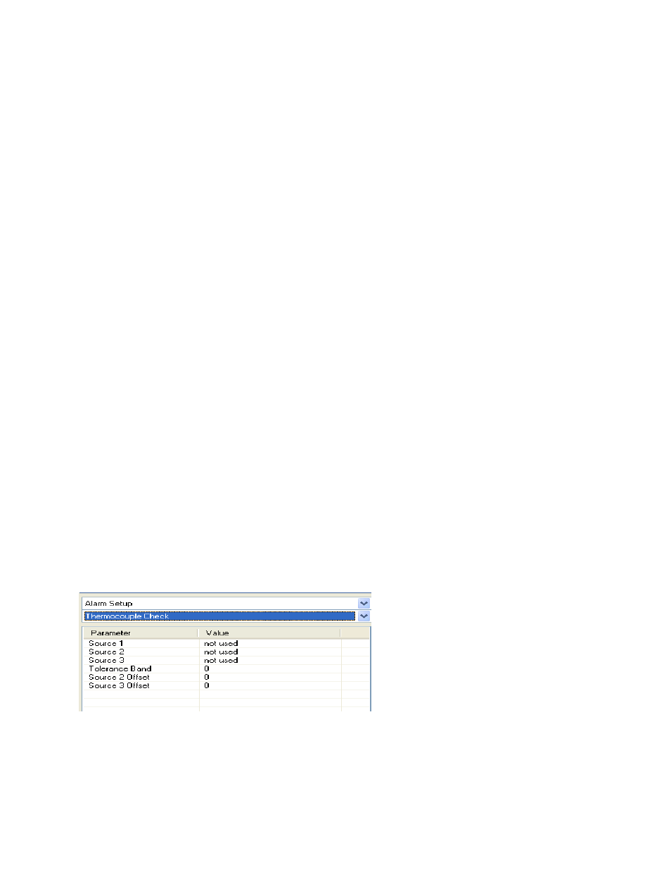
Thermocouple Check
Configurator – Alarm Setup Thermocouple Check menu option
Source 1 – Source 3:
These are the values for the first, second, and third source. The options are: not used,
Instrument 1 – Instrument 27, n/a, or Input 3 – Input 1.