Analog input correction curves, Instrument calculation – Super Systems 9205 Series User Manual
Page 77
Series 9205 Operations Manual Rev A
76
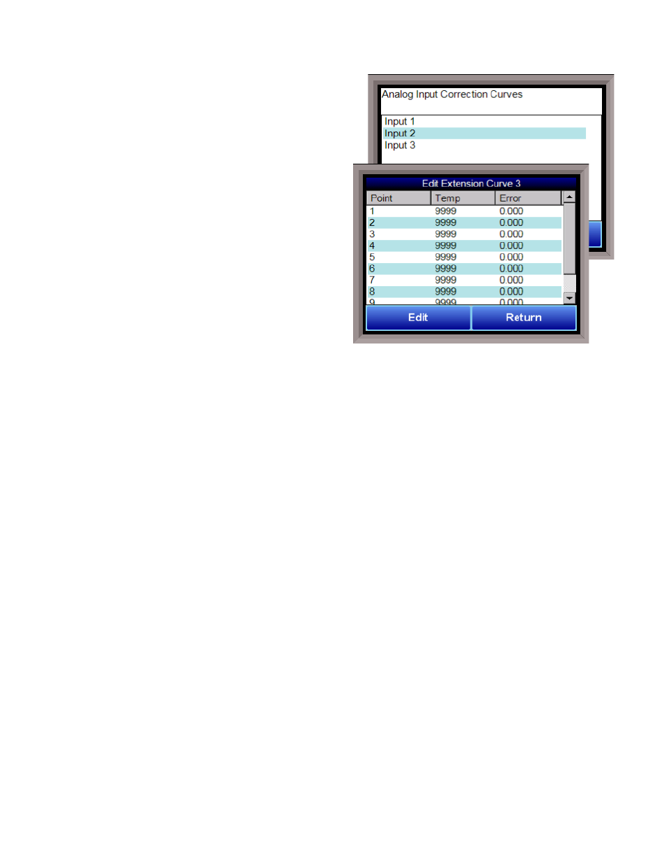
Analog Input Correction Curves
This option allows the user to edit a curve on an input 1,2,
or 3 at a specific temperature point. Select the
appropriate curve and press Edit to customize specific
points.
Select the point to be changed, and press Edit again.
Input the correct Temperature and Error, and press OK
to save.
Instrument Calculation
The Instrument Calculation menu allows programming
code-like lines to be executed at a variable time
interval per step.
Note: It is important to contact Super
Systems at (513) 772-0060 before creating or modifying
any Instrument Calculation customization
.
General Description
The Instrument Calculation allows for fifty (50) lines of
program and fifty (50) program variables. Program
variables allow for storage on intermediate results of
calculations.
A program variable is designated by a v followed by a number from 0 to the number of variables – 1.
A Lower or Upper case “V” is valid, as well as leading zeroes. The following are all considered the same
variable: V3, v3, v0003.
The 9205’s Modbus registers can be used as input variables in the equations without restriction. To protect
the instrument, Modbus registers are restricted as output registers.
Modbus registers are designated by an upper or lower case “M” followed by a number.
Note – The standard Modbus routine is called to retrieve the Modbus variable, therefore a 0x8000 (-32768)
will be returned for an invalid register
.
Note – Modbus registers are stored with integer values, so adjustments will need to be made for decimal
values
.
If the instrument can have external analog input boards, or the instrument is a Video Recorder or DAQ,
these inputs can be accessed directly as A1 through A40. By using the “A” designation, the Modbus register
number is not needed and the variable is scaled to the correct value (decimals included) based on the input
type specified.
In a Video Recorder, the slave instrument data slots can be defined as variables D1 through D32. D31 and
D32 are extra slots and have no restrictions as output variables. D1 through D30 are shared with the first
ten (10) slave instruments in groups of three (3) – PV, SP, PO – and caution should be used when assigning
as outputs.
A line in the program of the instrument calculation must start with a variable or a keyword.
Variables must be followed by an equal sign (=) and then an expression. The expression can be a simple
assignment (V1 = 3) or a variable operation variable as described below (V1 = M225 * 0.1).
Keywords
MUST
be entered in capital letters only.
The list of valid keywords is: IF, ELSE, ENDIF, QUE, RLY, and END.
“IF” must be followed by an expression which is a variable, relationship operator, then variable.
The list of valid relationship operators is: > (Greater Than), < (Less Than). = (Equals), >= (Greater Than or
Equal To), <= (Less Than or Equal To), != (Not Equal To), and == (Equal To).
Note – The “=” and “==”
relationship operators are identical
.
The list of valid bitwise operators is: & (AND), | (OR), ^ (XOR), << (Left Shift), and >> (Right Shift).
The result of the “IF” relationship test determines if the lines following the “IF” statement will be executed
or not.
The “ELSE” and “ENDIF” must be on a line by themselves. “ELSE” will toggle the program based on the
result of the “IF” test. “ENDIF” will close out the “IF”.