Analog input setup – Super Systems 9205 Series User Manual
Page 50
Series 9205 Operations Manual Rev A
49
Relay Output 8 – terminals 7 and 15 NC
Relay Output 8 – terminals 7 and 16 NO
Relay Output Choices
Loop 1 fwd
IN1 Relay SP A
Loop 1 rev
IN1 Relay SP B
Loop 2 fwd
IN1 Relay SP C
Loop 2 rev
IN2 Relay SP A
Loop 3 fwd
IN2 Relay SP B
Loop 3 rev
IN2 Relay SP C
Programmer alarm
IN3 Relay SP A
Alarm 1 – 3
IN3 Relay SP B
Event 0 – 15
IN3 Relay SP C
Burnoff
IR sample solenoid
0 – 47 Programmer 1
0 – 47 Programmer 2
nothing
The “Alarm Combination” option will allow the user to select the specific combination of alarms to use.
The options are: Programmer, Alarm 1, Alarm 2, Alarm 3, Invert State for Relay, and one of three options in
a drop-down box: TC Chk (Thermocouple Check), EOQ (End of Quench), or Programmer 2.
The Return button will return the user to the menu screen.
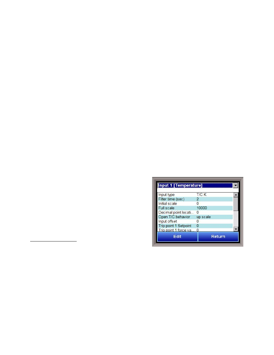
Analog Input Setup
The 9205 controller has three analog inputs. Each of the
inputs comes with a factory default configuration
dependent on the application. It can be modified prior to
shipment to your facility or in the field by a technician or
qualified/trained person with the proper security code.
Before connecting your input source to the terminals,
please verify that the input type is set up correctly. If the
Input Type is not correct, do not connect the input source to
the terminals, as damage can occur. Please consult SSi by
calling (513) 772-0060 before making any changes.
Analog Input Terminals
Analog Input 1 – terminals 31 and 32
Analog Input 2 – terminals 29 and 30
Analog Input 3 – terminals 27 and 28
Input Type
The thermocouple type for most applications can be modified depending on your specific needs.
Note -
some of the inputs DO NOT allow the user to modify the Input type
. To change the Input type, first select
which input you want to change by selecting it in the pull-down at the top of the screen. The following is a
list of the options:
B
S
12.5 volts **
C
T
781.25mV
E
2.5 volts
195.3125 mV
J
1.25 volts
K
78.125 mV
N
19.53125 mV