Tc type mv range chart, Calibration, Overview – Super Systems 9205 Series User Manual
Page 60: Equipment needed, Notes
Series 9205 Operations Manual Rev A
59
Instead, use any kind of regular sensor wire, or even regular copper wire. To perform the calibrations, the
user will need a calibrator that is capable of outputting volts, millivolts, and temperature.
The “Zero/Span” tab will allow the user to perform a zero and span calibration on the selected board.
The help button -
- next to the “Range” drop-down list will allow the user to select a range based upon
an input type if the range is not known.
Select the input type and click on the OK button. The correct millivolt range will be displayed in the drop-
down list. Click on the Cancel button to cancel this action.
Below is a listing of the suggested ranges for the various TC types.
TC Type mV Range Chart
TC Type
Range in mV
B
17.5
C
65
E
65
J
65
K
65
N
65
NNM
65
R
65
S
17.5
T
65
Calibration
For calibration videos involving the touch screen, visit
Overview
The series 9205 can be calibrated using the
Touchscreen interface. Before performing this
procedure on a newly installed controller, the unit
needs to be powered on for at least 30 minutes for a
warm up period.
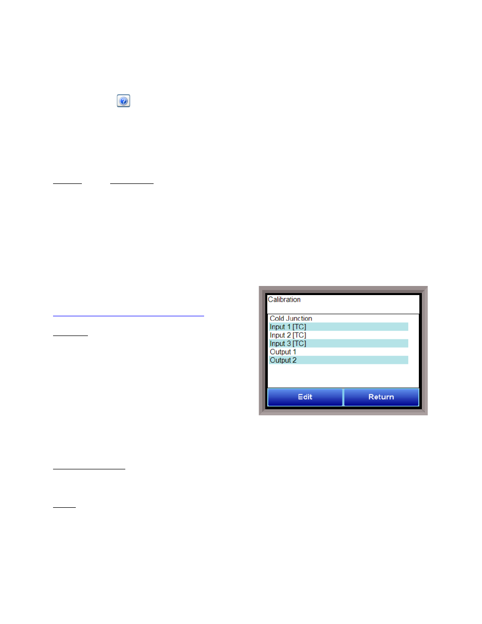
The series 9205 has three analog inputs. Each range has
a zero and span calibration value. A cold junction trim
value must be calibrated for thermocouple inputs. There
are two analog outputs each with a zero and span value.
To calibrate an input or output, select the desired option and continue.
Note – Even though the “Cold
Junction” option is listed first, the inputs and outputs should have the zero and span calibration performed
BEFORE performing a cold junction calibration
.
Equipment needed
A certified calibrator(s) with the ability to input and read millivolts, milliamps and thermocouples is
required. The appropriate connection leads are also required. A 24VDC 75-watt power supply is required.
Notes
Input 1 – terminals 31 and 32
Input 2 – terminals 29 and 30
Input 3 – terminals 27 and 28
Output 1 – terminals 24 and 25
Output 2 – terminals 25 and 26