Analog output setup – Super Systems 9205 Series User Manual
Page 52
Series 9205 Operations Manual Rev A
51
Trip Point 2 Setpoint
This is the trip point 2 setpoint value. The range is –32768 to 32767.
Trip Point 2 Force Value
This is the trip point 2 force value. The range is –32768 to 32767.
Trip Point 2 Direction
This is the trip point 2 direction. The options are: input above setpoint or input below setpoint.
High Input Limit Setpoint
This is the setpoint for the high input limit. The range is –32768 to 32767.
High Input Limit Hysteresis
This is the hysteresis for the high input limit. The range is –32768 to 32767.
Custom Curve
This will allow the user to set the custom curve to use. The curves are set up through the C
urve Entry
menu option. The options are: None, Curve 1 – Curve 3.
T/C Correction Curve
This will allow the user to set the T/C correction curve to use. The curves are set up through the
T/C
Correction Curves
menu option. The options are: None, Curve 1 – Curve 3.
The Return button will return the user to the menu screen.
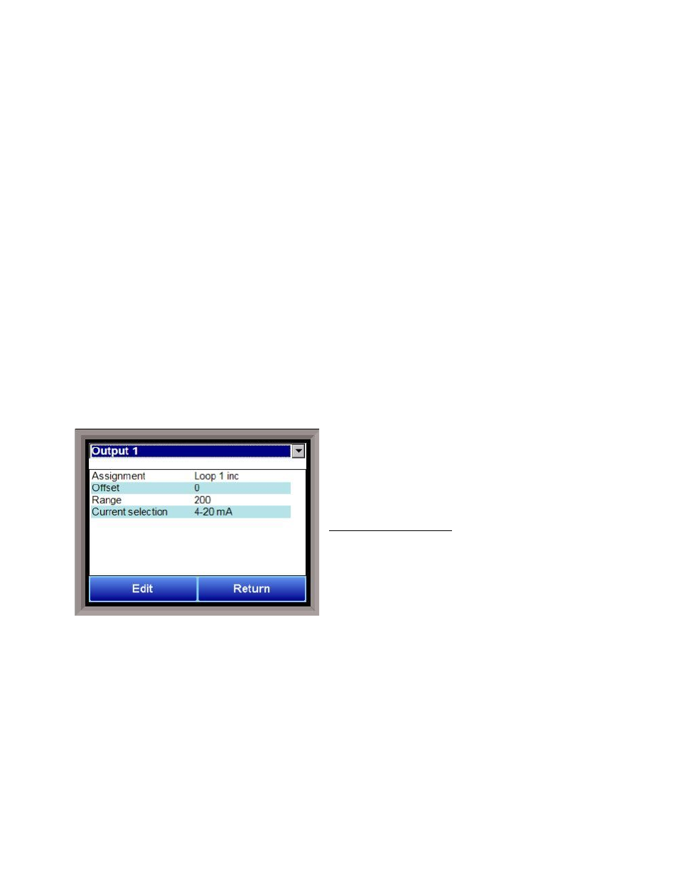
Analog Output Setup
The 9205 controller has the option of six analog
outputs. The outputs are ranged for a 4 – 20 milliamp
signal or a 0 – 20 milliamp signal. Each output comes
with a factory default configuration dependent on the
application. Each output can be modified prior to
shipment to your facility or in the field by a supervisor.
Analog Output Terminals
Analog output 1 – terminals 24 and 25
Analog output 2 – terminals 25 and 26
Analog outputs 3, 4, 5, and 6 are enabled by use of an
SSi QuadDAC board that connects to two RS485
terminals on the 9205 (terminals 5 and 6 for Slave 1,
terminals 22 and 23 for Slave 2). Use the
Port Setup menu to configure communication parameters.
Assignment
The analog output assignment can be modified depending on your system requirements. To change the
Assignment first select which analog output you want to change by selecting it in the pull-down menu at the
top of the screen. The following is a list of the options:
PV 1 retrans
Loop 1 inc
Loop 1 dec
Loop 1 combo
PV 2 retrans
Loop 2 inc
Not assigned
O2 offset log
SP1 retrans
SP2 retrans
SP3 retrans
Programmer ID number
Programmer DAC 5
Programmer DAC 6
Prog 2 Quench speed (0-1000=0-100%)
Programmer 2 DAC 1
Programmer 2 DAC 2
Programmer 2 DAC 3