Thermocouple check, Relay assignments – Super Systems 9205 Series User Manual
Page 49
Series 9205 Operations Manual Rev A
48
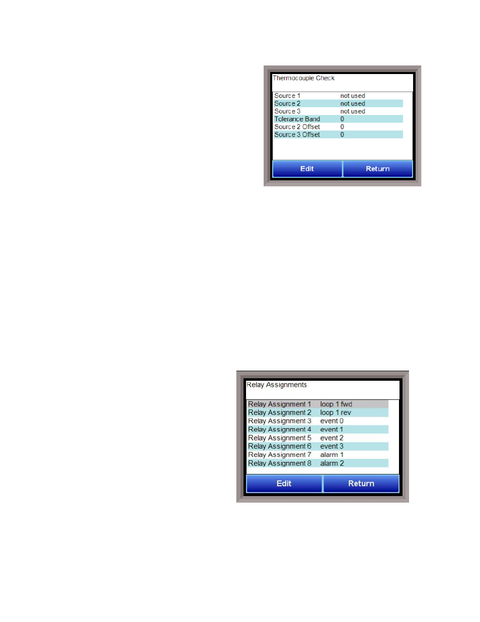
Thermocouple Check
This menu option allows the values between up to three
thermocouples to be compared to one another. If the
thermocouples go out of band, it is possible to set up an
alarm that will alert the operators of this error.
Source 1 This assigns the first thermocouple that will be
compared. The options are:
Not used
Instrument 1-27
Input 1 - 3
Source 2 This assigns the second thermocouple that will
be compared. The options are:
Not used
Instrument 1-27
Input 1 – 3
Source 3 This assigns the third thermocouple that will be compared. The options are:
Not used
Instrument 1-27
Input 1 – 3
Tolerance Band This allows the operator to set the tolerance band between the thermocouples being
compared. The range is -9999 to 9999.
Source 2 Offset This allows for an offset to be assigned to the second thermocouple and taken into account
when the comparison between values is made. The range is -9999 to 9999.
Source 3 Offset This allows for an offset to be assigned to the third thermocouple and taken into account
when the comparison between values is made. The range is -9999 to 9999.
Relay Assignments
The 9205 controller has eight relay outputs, as
well as eight relay outputs for four additional
modules. All of the relays have a positive common
terminal and independent negative terminals. All
of the relays are configured in a normally closed
position except relay number eight, which has
both a normally closed (NC) and a normally open
(NO) terminal. These relays can be configured to
work with events, alarms, loops, burnoff and
alarm combinations.
Relay Output Terminals:
Relay Output 1 – terminals 7 and 8
Relay Output 2 – terminals 7 and 9
Relay Output 3 – terminals 7 and 10
Relay Output 4 – terminals 7 and 11
Relay Output 5 – terminals 7 and 12
Relay Output 6 – terminals 7 and 13
Relay Output 7 – terminals 7 and 14