Ssi configuration and calibration, Overview, Equipment needed – Super Systems 9205 Series User Manual
Page 119: Notes, User calibration, Onfiguration and, Alibration
Series 9205 Operations Manual Rev A
118
SSi Configuration and Calibration
Overview
The series 9205 can be calibrated using the Instrument Configurator software supplied with the system.
Before performing this procedure on a newly installed controller, the unit needs to be powered on for at
least 30 minutes for a warm up period.
The series 9205 has three analog inputs. Each range has a zero and span calibration value. A cold junction
trim value must be calibrated for thermocouple inputs. There are two analog outputs each with a zero and
span value.
Equipment needed
A certified calibrator(s) with the ability to source and read millivolts, milliamps and thermocouples is
required. The appropriate connection leads are also required. The operator interface method requires a PC
with the Configurator software loaded. An Ethernet crossover cable is required.
Notes
Input 1 – terminals (-) 31 and (+) 32
Input 2 – terminals (-) 29 and (+) 30
Input 3 – terminals (-) 27 and (+) 28
Output 1 – terminals (-) 24 and (+) 25
Output 2 – terminals (-) 25 and (+) 26
Calibrate Aux Analog Input
If an SSi analog input board is set up, then this menu option will be visible. For information on how to
calibrate an SSi analog input board, see the Calibrate Aux Analog Input section located at the end of this
section.
User Calibration
Click on the “click” value next to the “9205 User Calibration” field to start the user calibration. The
Calibration screen will be displayed. For complete calibration of Analog Inputs start with step #1, Zero and
Span Calibration. The Cold Junction Calibration should be performed AFTER the user has calibrated all of
the inputs and, if needed, outputs.
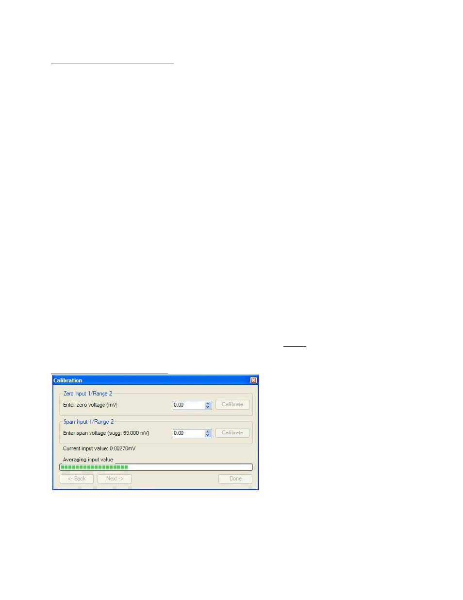
Step 1. Zero then Span Calibration.
The second screen (Zero/Span Calibration),
and all of the subsequent screens, will
allow the user to zero and span calibrate
the inputs and outputs for the 9205
controller (cold junction calibration will be
performed as a final step).
For a zero calibration, a value of 0 mV will
need to be sourced to the input or inputs.
In the “Zero Input X/Range Y” section,
enter the zero voltage and click on the
Calibrate button. This will calibrate the
zero range. The progress of the calibration will be shown in the progress bar at the bottom of the screen.
For a span calibration, a value of 90% of the full range (or the adjusted value) will need to be sourced to the
input or inputs.