Super Systems AC20 User Manual
Page 9
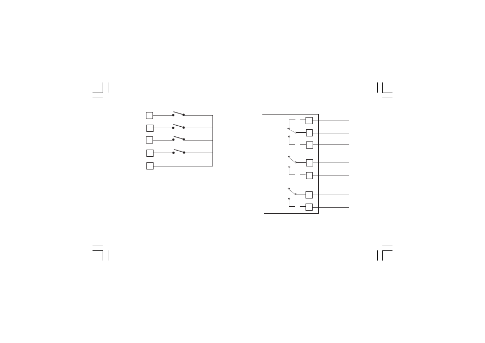
7
47
48
45
IN 6
IN 7
46
IN 5
49
IN 8
Fig. 7.B - LOGIC INPUTS IN5 TO IN8 WIRING
Logic inputs from IN1 to In8 are optional.
NOTES
NOTES
NOTES
NOTES
NOTES:
1) Do not run logic input wiring together with power cables.
2) Use an external dry contact capable of switching 0.5 mA,
5 V DC.
3) The instrument needs 110 ms to recognize a contact status
variation.
4) The logic inputs are NOT
NOT
NOT
NOT
NOT isolated from measuring inputs.
C.1) RELAY OUTPUTS
C.1) RELAY OUTPUTS
C.1) RELAY OUTPUTS
C.1) RELAY OUTPUTS
C.1) RELAY OUTPUTS
Fig. 8.A RELAY OUTPUTS 1, 2, 3 WIRING
OUT 1
23
NC
24
C
25
NO
OUT 2
26
C
NO
27
OUT 3
28
C
NO
29
See also other documents in the category Super Systems Equipment:
- Bazooka Probe (10 pages)
- Gold Probe (16 pages)
- HP2000 With 9100 Controller (10 pages)
- HP15 (23 pages)
- SuperOX (14 pages)
- PGA3000 (16 pages)
- PGA3500 (26 pages)
- e-TRIM (27 pages)
- 9120 with TS (80 pages)
- MGA6000 (42 pages)
- DP2000 (17 pages)
- DPC3500 (5 pages)
- MGA6010 (54 pages)
- DPC2530 (17 pages)
- Simple Dew (18 pages)
- DPL4000 (16 pages)
- H2 Sensor (17 pages)
- Hydrogen Nitrider Analyzer (12 pages)
- PH2 (19 pages)
- AC20 Quick Start (5 pages)
- XGA Viewer (46 pages)
- AC20 RS485 Modbus (62 pages)
- 20Q Calibration Manual (9 pages)
- CAT-100 (51 pages)
- 7EK 31080 (32 pages)
- 7EK 31082 Calibration Manual (5 pages)
- 7EK 31081 (36 pages)
- 7EK 31082 (34 pages)
- 20PQ (170 pages)
- X5 Calibration Manual (1 page)
- 20Q (126 pages)
- 7SL (36 pages)
- X5 (74 pages)
- 9000 Series (15 pages)
- 3L Series (54 pages)
- 9015 Series (11 pages)
- 3 Series (92 pages)
- 9010 Series (66 pages)
- 9210 Series (65 pages)
- 9130 Series (174 pages)
- PC Configurator 2 Quick Start (15 pages)
- 9100 RPS (10 pages)
- 9125 Series (235 pages)
- 9120 RPS (11 pages)