P2 digital i/o – Measurement Computing LogBook Series User Manual
Page 52
4-8 System Expansion
957096
LogBook User’s Manual
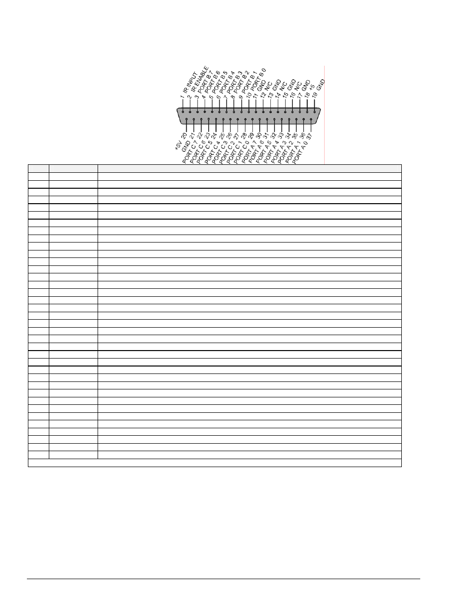
P2 Digital I/O
Pin
Signal Name
Description for P2 Pin Use
1
IR INPUT
Interrupt line input (no functions to access this)
2
IR ENABLE
Interrupt line enable (no functions to access this)
3
PORT B 7
Digital input/output – port B bit 7
4
PORT B 6
Digital input/output – port B bit 6
5
PORT B 5
Digital input/output – port B bit 5
6
PORT B 4
Digital input/output – port B bit 4
7
PORT B 3
Digital input/output – port B bit 3
8
PORT B 2
Digital input/output – port B bit 2
9
PORT B 1
Digital input/output – port B bit 1
10
PORT B 0
Digital input/output – port B bit 0
11 GND
Digital
ground
12
N/C
Pin not connected/not used
13 GND
Digital
ground
14
N/C
Pin not connected/not used
15 GND
Digital
ground
16
N/C
Pin not connected/not used
17 GND
Digital
ground
18
+5 V
+5 V supply @ 0.100 A
19 GND
Digital
ground
20
+5 V
+5 V supply @ 0.100 A
21 GND
Digital
ground
22
PORT C 7
Digital input/output – port C bit 7
23
PORT C 6
Digital input/output – port C bit 6
24
PORT C 5
Digital input/output – port C bit 5
25
PORT C 4
Digital input/output – port C bit 4
26
PORT C 3
Digital input/output – port C bit 3
27
PORT C 2
Digital input/output – port C bit 2
28
PORT C 1
Digital input/output – port C bit 1
29
PORT C 0
Digital input/output – port C bit 0
30
PORT A 7
Digital input/output – port A bit 7
31
PORT A 6
Digital input/output – port A bit 6
32
PORT A 5
Digital input/output – port A bit 5
33
PORT A 4
Digital input/output – port A bit 4
34
PORT A 3
Digital input/output – port A bit 3
35
PORT A 2
Digital input/output – port A bit 2
36
PORT A 1
Digital input/output – port A bit 1
37
PORT A 0
Digital input/output – port A bit 0
Note: No local lines are available if digital expansion cards are in use.