Help box …… lv-7 user input…… lv-7 – Measurement Computing LogBook Series User Manual
Page 133
Software Reference
989592
LogView LV-7
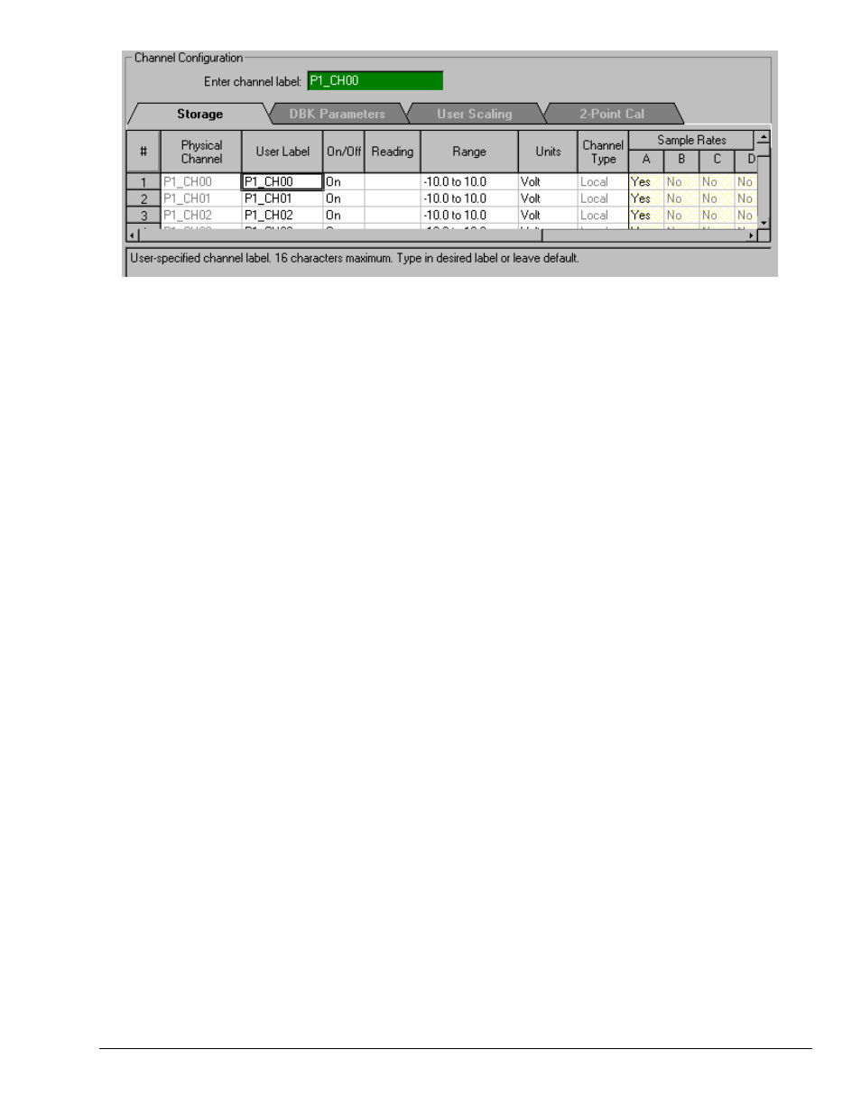
Analog Input Channel Configuration Window, Spreadsheet Portion
LogView’s spreadsheet-style setup provides a simple method of both viewing and configuring the
parameters of the input, output, and calculated channels. Several spreadsheets are needed to display all the
channels’ parameters. LogView’s spreadsheet windows include:
•
Analog Input Channel Configuration
(see page LV- 30 for details) - This default-opening window
has more parameter columns than will fit in view at one time. Therefore, the left-most (white)
columns are shown in every view; these parameters include: Physical Channel, User Label, On/Off,
Reading, Range, Units, and Channel Type. The right-most (shaded) columns vary depending on
which folder tab is selected. Each tab (Storage, DBK Parameters, User Scaling, and 2-Point
Calibration) has
tab-specific parameters.
•
Digital and Counter Input Channel Configuration
(see page LV-34) - LogBook has three 8-bit
digital ports and one high-speed 16-bit port configurable as inputs or outputs. Digital expansion
cards can provide up to 192 digital bits. There are also 4 pulse-input ports that can count pulses for
summing and/or frequency measurement.
•
Output-Channels Configuration
(see page LV-35) - This window shows all the currently-available
digital and analog output channels. Each output channel is fed by a user-set source channel. Source
channels can be chosen from any of the input (hardware) channels or calculated (virtual) channels.
•
Calculated-Channel Configuration
(see page LV-36) - LogView can derive virtual channels using
standard math operators and functions (<, >, min, max., etc.). Virtual channels can be used to create
alarms, reduce data statistically, develop sophisticated trigger equations, and manipulate input
channel values for more useful output including simple control systems.
Help Box
The bottom of the spreadsheet contains a context sensitive Help Box for the selected field. As you
configure channel parameters, the Help box identifies the field and provides pertinent user information.
An example, taken from the previous figure, follows.
Example: In the above figure the User Label cell (of channel 1) is selected. The Help box identifies the
field as “User-specified channel label” and states user options. In this case, they are (1) to type
in a desired label, i.e., to provide the channel with more meaningful name [not to exceed 16
characters]; or (2) keep the default label of P1_CH00.
User Input
To set up channel parameters, first select the appropriate cell (highlighted in a bold box) with the mouse or
keyboard arrow keys (up/down/sideways). Some cells allow you to key-in values from a keyboard (values
such as user labels, offsets, etc.). When key-in cells are selected, a user-input box will appear where you
can type in characters as needed (e.g., channel label in previous figure). Some cells allow you to choose
the desired setting from a drop-down list; you select among the options, and the parameter is set. Other
cells allow you to set numeric values with “spinner” up/down arrows that change the value incrementally
(selecting a point between the spinners changes the mouse action into a virtual scroll bar—as you drag the
mouse vertically, the numeric values change accordingly).