Measurement Computing LogBook Series User Manual
Page 106
7-4 Using Modems and the Upload Scheduler
958896
LogBook User’s Manual
The configuration download cannot be accomplished via a serial port connection.
This is because once the modem configuration is downloaded to the PC-Card in
the LogBook, the LogBook will no longer be capable of serial port
communication directly with the PC.
Reference Note:
If needed, refer to additional PC-card information in chapter 1 and in the LogView
section of this user’s manual.
8. Upon completion of the download, close LogView.
Step X.2 – Set up the Modem
Desktop modems
Refer to your modem user’s manual to verify whether the device has any DIP-switches. If a DIP-switch is
present and is set for DTR, set it to DTR Override. When DTR Override is set, the DR (Data Ready) LED
will light up after turning the modem on.
Note: It is recommended that your modem be set for “auto-answer,” if it is equipped with this feature.
Cellular modems
Refer to the user documentation that is specific to your modem. Set the cellular modem for auto answer.
Step X.3 – Physically Connect the Modem to the LogBook
1. If your LogBook has the LBK/COM/422/485 option installed, verify that the option is set for RS-232
communication. The option is discussed in chapter 5. (See following note).
If you are using the LBK/COM/422/485 communications option you will need to
ensure that the option board is positioned on LogBook’s internal slot “CN8” such
that the RS-232 communication mode is enabled. If your LogBook has the
LBK/COM/422/485 option and you are uncertain about the communication mode,
refer to chapter 5, LBK and other non-DBK options. The chapter section entitled
LBK/COM/422/485
explains how to set the communications option for RS-232.
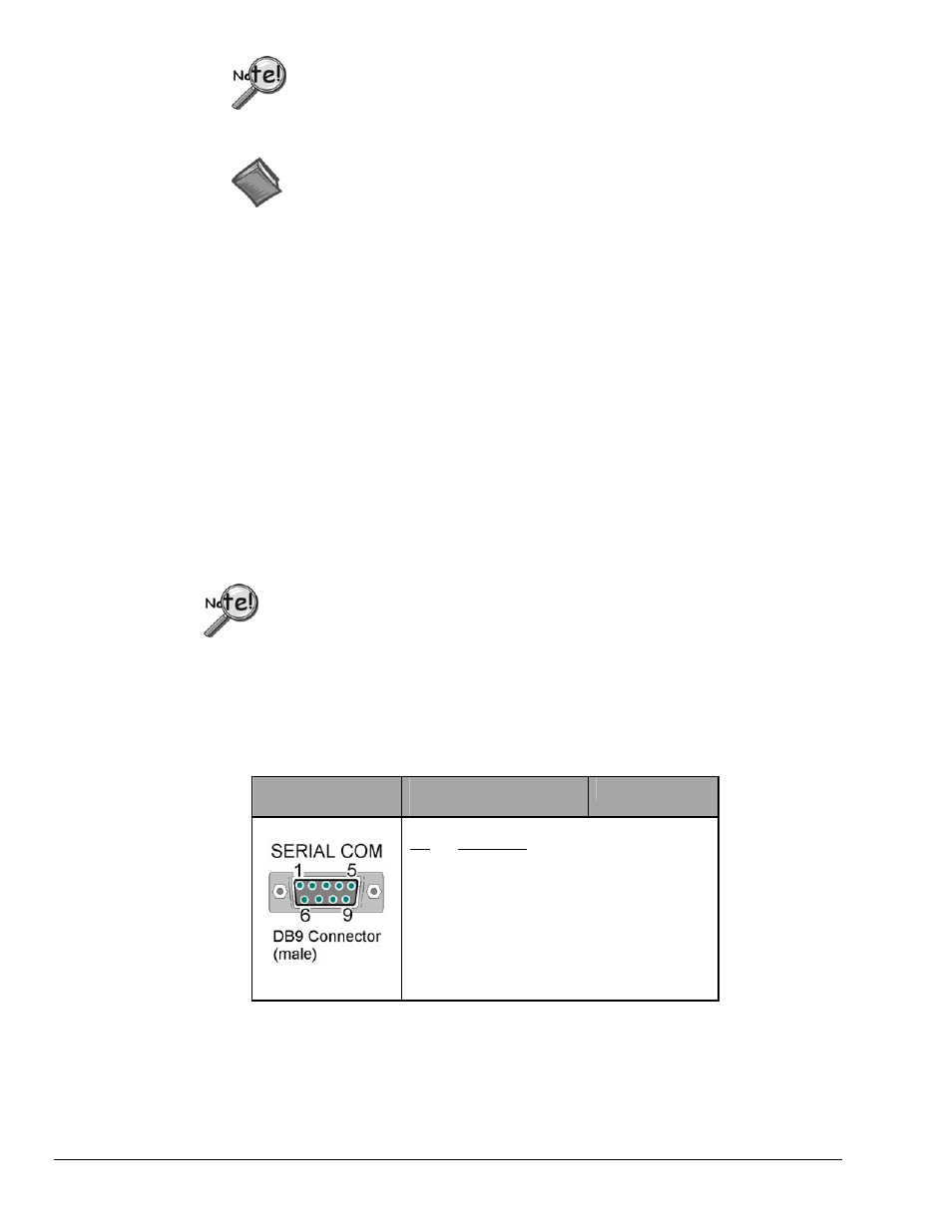
2. Connect the modem to the LogBook’s 9-pin Serial COM port. RS-232 mode is required.
9-Pin Connector
On LogBook
LogBook’s Serial COM
Pinout
Modem Signals
Pin
1
2
3
4
5
6
7
8
9
Description
Not Used
RxD ------- connects to --- TxD
TxD --------connects to --- RxD
Not Used
Common ---connects to -- Common
Not Used
RTS ---------connects to ---CTS
CTS ---------connects to --- RTS
Not Used
Modem Connection to LogBook’s Serial COM Port
3. Turn power on to the LogBook and the modem. The LogBook will automatically send the specified
command string, if applicable.
Note that some modems have an LED to indicate that the device is in “auto-answer” mode and /or that
the modem is being initialized.