Caution, Hardware configuration – Measurement Computing LogBook Series User Manual
Page 40
LogBook/360 Quick Start Guide
QS360
-
7
c) Serial port to USB port - Requires an adapter kit. To connect the LogBook to a USB port you will need a
RS-232 to USB Interface Adapter Kit p/n CA-232-USB-KIT (available from Measurement Computing).
Refer to the associated Quick Start document (QS RS-232_to_USB_Interface.pdf) for a list of the kit’s contents
and for RS-232 to USB conversion instructions. The pdf is included on Data Acquisition CD (rev 8.1.2 and
higher).
d) PC-Card – With PC-Card communication, LogBook/360 does not require a connection to the computer, as
communication is accomplished via the PC-Card. To provide the PC-Card with the correct configuration
file, it must be configured from the PC, through LogView. After the PC-Card is configured, it is inserted
into LogBook’s PC-Card slot, located behind the front panel door.
Reference Note:
Information pertaining to PC-Cards can be found in chapter 1 and in the LogView section of the
LogBook User’s Manual PDF.
2. Connect LogBook/360 to the DBK cards and modules. For connecting internal DBK cards, refer to
the earlier section entitled, Setting Up the Card Drawer.
Most analog DBKs connect to P1; digital DBKs generally connect to P2. Refer to the DBK Options
Manual (457-0905) in regard to your particular DBKs and for general DBK installation details.
The CA-37-x cable can daisy-chain several DBKs including the DBK41, which has a built-in
P1 bus connection for 10 DBK cards. The x in the cable part number refers to the number of devices
that can be connected (a CA-37-1 actually has two DB-37 connectors).
Note: Chapter 4 of the LogBook User’s Manual PDF includes pinouts for LogBook/360’s P1, P2,
and P3 connectors.
CAUTION
For analog signal inputs via P1, do not exceed -35 VDC or +45 VDC.
Exceeding these limits could result in equipment damage.
3. Connect DBK(s) to transducer(s). Follow instructions for particular DBK as described in the
DBK Option Cards & Modules User’s Manual and for the particular transducer. Some DBKs can
accommodate both BNC and screw-terminal connections.
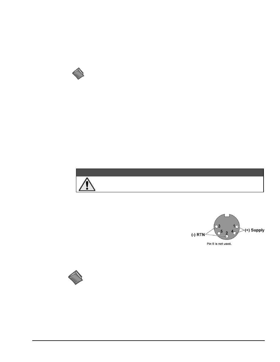
4. Connect LogBook/360 to a suitable power source, such as
the included AC-to-DC adapter or optional DBK34A
UPS / Battery Module. DC power sources such as a car
batteries must supply 10 to 45 VDC and use the correct
DIN5 pinout (see figure). A locking DIN5 connector
assures a secure power connection for applications subject
to vibration and thermal stress.
DIN5 Power Input Connector
(
As seen on LogBook/360 Front Panel)
Hardware Configuration
Reference Notes:
Refer to the device-specific sections of the LBK options chapter [in the user’s manual PDF]
and the DBK Option Cards & Modules User’s Manual PDF for information regarding these
devices. Note that certain DBK options require manual configuration.
LogBook/360's top cover does not need to be removed, except to add or remove an LBK option, or to
replace the fuse.
Most LogBook/360 configuration is done via software as described in section, LogBook/360 Device
Configuration. LogBook/360 configuration does not require the setting of jumpers or switches, unless
the RS-485 communication option is being used.