Measurement Computing LogBook Series User Manual
Page 38
LogBook/360 Quick Start Guide
QS360
-
5
7 – Install power card if necessary.
If you determined in step 5 that additional power was needed, add a DBK32A or DBK33 power card to the
chassis. The DBK Option Cards & Modules User’s Manual includes detailed information regarding these
power-related cards.
A. Carefully align the power card’s DB37 connector with a DB37 connector on the interconnect board and
gently press them together.
B. Mount the power card with two screws into the standoffs on the card drawer.
8 – Configure DBK cards.
Configure unique channel addresses with the jumpers on the DBK cards. Some cards have other jumpers and/or
DIP switches. Refer to the specific DBK sections of the DBK Options Manual (p/n 457-0905) as needed.
9 – Install DBK cards.
You must use all analog DBK cards in the LogBook/360; unless you have a factory modification that allows the
use of all digital cards. You can not use both analog and digital cards at the same time.
A. Carefully align the DBK card’s DB37 connector with a DB37 connector on the interconnect board and
gently press them together (see figure).
B. Mount the DBK card with two screws into the standoffs on the card drawer (see previous figure).
C. Continue installation of any remaining DBK cards.
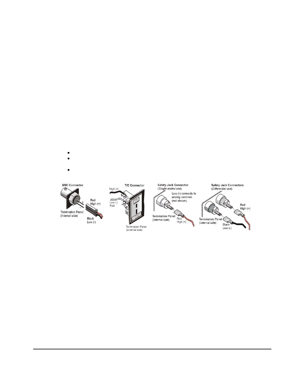
10 – Connect internal signals.
Connect signal inputs from DBK cards to termination panels. DBK cards connect to the termination panels in
various ways (see figure and particular DBK sections in the DBK Option Cards and Modules User’s Manual):
Single-ended connections use analog common.
Differential connections require the proper polarity, typically red-to-red for high (+)
and black-to-black for low (-).
For thermocouples, red is generally the low side. Always make sure the T/C connector and wire type
match the T/C type used.
11 – Install termination panels.
Mount the termination panels to the card drawer with two screws for each panel.
12 – Install card drawer.
The card drawer slides into the bottom track of the chassis.
A. Hold the card drawer by its handle and tilt it up slightly. Place it on the bottom track of the chassis.
B. Carefully slide the card drawer into the chassis. When it engages the bottom track, level the card drawer and
continue inserting it until it engages with the P1 interconnect board.
C. Tighten the three captive thumbscrews holding the termination panels to the chassis.
D. Install the two screws holding the card drawer to the chassis.
13 – Connect external signals.
Connect signal inputs from sensors to termination panels.
14 – Install top cover.
If the top cover was removed, slide it back into place and secure with two screws.