Comtech EF Data LBC-4000 User Manual
Page 133
LBC-4000 L-Band Up/Down Converter System with Ethernet
Revision 2
Appendix B
MN-LBC4000A
B–3
B.3
Redundancy Operations via the LBC-4000 Front Panel
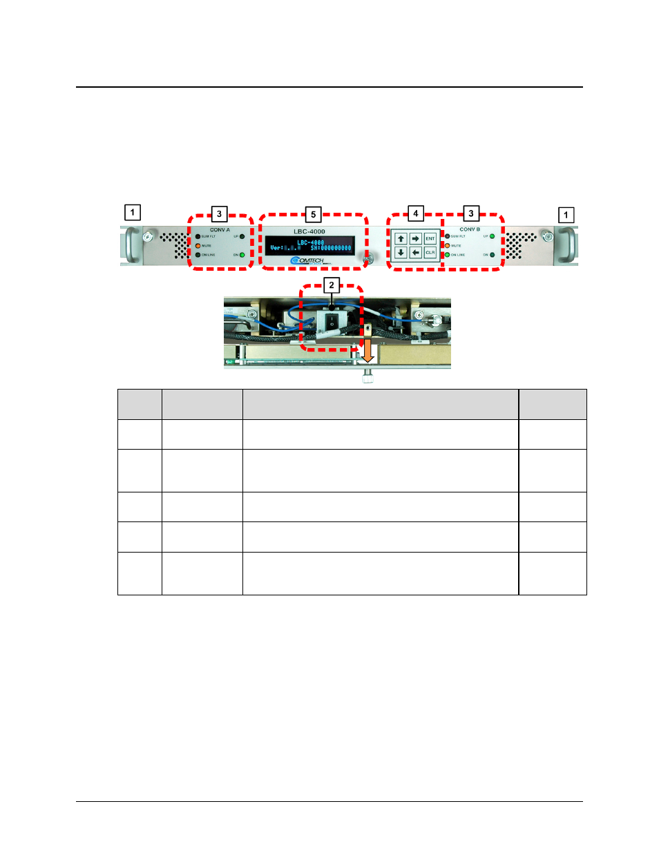
You can configure, monitor, and control redundancy operation via the LBC‐4000 front panel,
using the keypad and display. Nested menus are used, which display all available options, and
prompt you to carry out a required action. Figure B‐3 identifies the key features of the LBC‐4000
front panel; see Chapter 5. FRONT PANEL OPERATION for in‐depth explanations of the function
and operation of this operational interface.
Feature Description
Function
See Chapter
Section...
1 Rack
Handles
The handles allow quick installation into and removal of the unit
from an equipment rack.
2.2
2
Prime Power
Switch
The Prime Power Switch is located inside the front panel rear
panel. Loosen the thumbscrews, slide the front panel out from the
chassis, and then swing down.
3.3.2.3
5.1.1
3
Converter LED
Indicator Group
The two groups of LEDs indicate, in a summary fashion, the status
of each converter.
5.1.2
4 Keypad
The keypad comprises six keyswitches behind a flat membrane.
Enter data via the keypad.
5.1.3
5
Vacuum
Fluorescent
Display (VFD)
The VFD is an active display showing two lines of 24 characters
each. It produces a blue light with adjustable brightness. Nested
menus, data, prompts, and messages are displayed on the VFD.
5.1.4
Figure B-3. LBC-4000 Front Panel