7 (j19) – Comtech EF Data SFC1800A User Manual
Page 75
SFC1800A Synthesized Frequency Upconverter
Rear Panel Interfaces
TM111 – Rev. 1.0
5-9
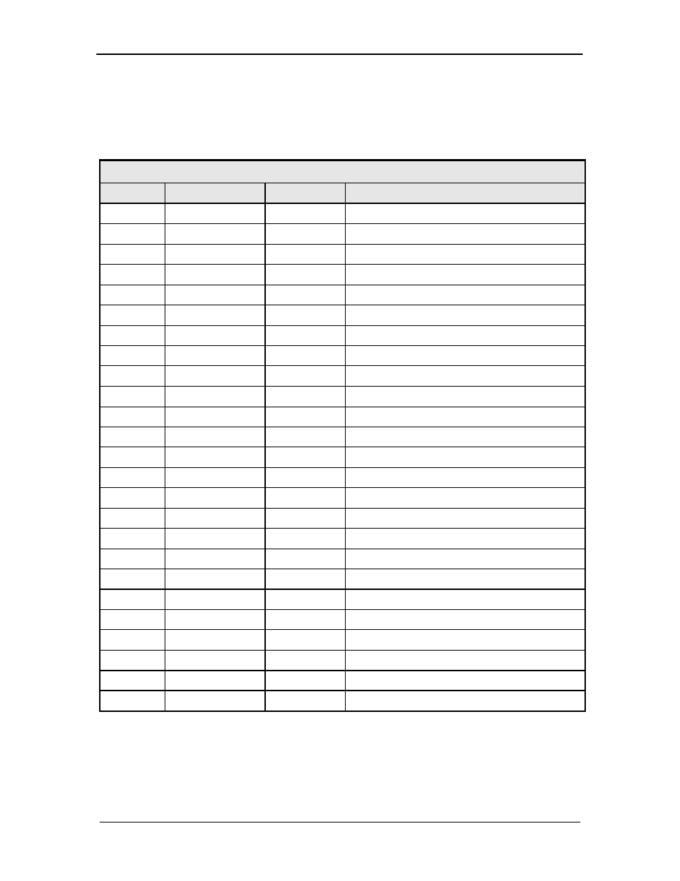
5.13.7 (J19)
J19 is a D Sub 25 Pin Female Connector that is a combination of the RS-484 and B/U Switch
Interfaces. This connector connects each converter in a daisy chain configuration with the
backup master converter.
Table 5-7. J19 – D-Sub 25-Pin Female Connector
Pin No.
Signal
I/O
Description
1
+15 V_SW
---
+15 VDC Power Bus
2
+15 V_SW
---
+15 VDC Power Bus
3
TX_485-A_SW
Out
Inverted RS-485 Transmit
4
RX_485-A_SW
In
Inverted RS-485 Receive
5
I2C_SDA_SW
I/O
I2C Data
6
ID_IN_SW0
In
Converter Position ID Bit 0
7
ID_IN_SW2
In
Converter Position ID Bit 2
8
FAULT_SW1
Out
Switch Fault Indicator – Prime 1
9
FAULT_SW3
Out
Switch Fault Indicator – Prime 3
10
FAULT_SW5
Out
Switch Fault Indicator – Prime 5
11
FAULT_SW7
Out
Switch Fault Indicator – Prime 7
12
GND
---
Ground
13
GND
---
Ground
14
+15 V_SW
---
+15 VDC Power Bus
15
N/C
---
No Connection
16
TX_485-B_SW
Out
RS-485 Transmit
17
RX_485-B_SW
In
RS-485 Receive
18
I2C_SCL_SW
Out
I2C Clock
19
ID_IN_SW1
Out
Converter Position ID Bit 1
20
ID_IN_SW3
Out
Converter Position ID Bit 3
21
FAULT_SW2
Out
Switch Fault Indicator – Prime 2
22
FAULT_SW4
Out
Switch Fault Indicator – Prime 4
23
FAULT_SW6
Out
Switch Fault Indicator – Prime 6
24
FAULT_SW8
Out
Switch Fault Indicator – Prime 8
25
GND
---
Ground