0 installation requirements, Installation – Comtech EF Data SFC1800A User Manual
Page 15
SFC1800A Synthesized Frequency Upconverter
Installation
TM111 – Rev. 1.0
2-1
Installation
2
2.0 Installation Requirements
The SFC1800A Upconverter is designed to be installed within any standard 19 inch equipment
cabinet or rack, and requires 1 Rack Unit (1RU) mounting space (1.75 inches, 4.44 cm) vertically
and 19 inches (48.26 cm) of depth. Including cabling, a minimum of 20 inches (50.8 cm) of rack
depth is required. The rear panel is has power enter from the left and cabling enter from the
center and right as viewed from the rear of the unit. Data and control cabling can enter from
either side. The unit can be placed on a table or suitable stable surface if required.
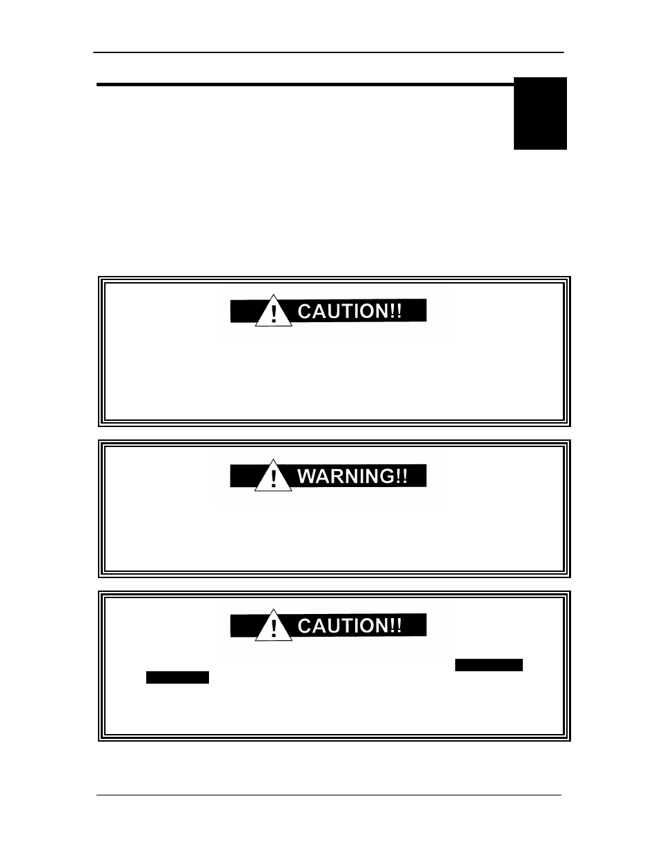
Before initially applying power to the unit, it is a good idea to disconnect
the transmit output from the operating station equipment. This is
especially true if the current SFC1800A Upconverter configuration
settings are unknown, where incorrect setting could disrupt existing
communications traffic.
There are no user-serviceable parts or configuration settings located
inside the SFC1800A Upconverter chassis. There is a potential shock
hazard internally at the power supply module. DO NOT open the SFC
Chassis under any circumstances.
The SFC1800A Upconverter contains a Lithium Battery.
DANGER OF
EXPLOSION
exists if the battery is incorrectly replaced. Replace only
with the same or equivalent type recommended by the manufacturer.
Dispose of used batteries in accordance with local and national
regulations.