4 front panel keypad, 5 led indicators – Comtech EF Data SFC1800A User Manual
Page 27
SFC1800A Synthesized Frequency Upconverter
User Interfaces
TM111 – Rev. 1.0
4-3
4.1.4 Front Panel Keypad
The front panel keypad consists of two areas: a 10-key numeric entry with 2 additional keys for
the ‘Enter’ and ‘Clear’ function. The second area is a set of ‘Arrow’ or ‘Cursor’ keys (
↑), (↓), (→),
(
←), used to navigate the parameter currently being monitored or controlled. Table 4-3 describes
the key functions available at the front panel.
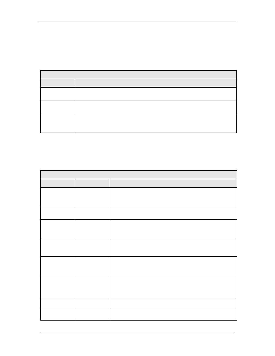
Table 4-3. Front Panel Keypad
Key
Function
0 to 9
The Number Keys are used to change numeric values in the value field of the
LCD display.
CLEAR
If pressed before
cause that parameter to return to its original value.
ENTER
The Enter Key will cause changes to Frequency, Status, and other operator-
selected parameters to be executed. It also causes the status of the converter
to be saved into non-volatile memory.
4.1.5 LED Indicators
There are twelve (12) LEDs on the SFC1800A Upconverter Front Panel to indicate the operation
status (refer to Table 4-3).
Table 4-3. Front Panel LED Indicators
LED
Color
Function
POWER
Green
When illuminated, indicates the presence of primary power
and that the On/Off Switch located on the rear of the chassis
is in the On Position.
FAULT
Red
When illuminated, Indicates a common fault (internal
hardware).
EVENT
Yellow
When illuminated, indicates that an event (may be a fault or
startup sequence) has occurred and is stored in the Event
Buffer along with a date/time stamp.
REMOTE
Green
When illuminated, indicates that the converter is in Remote
Mode. In this mode, the unit settings can only be modified
and controlled via a remote interface.
ONLINE
Green
When illuminated, indicates that the backup converter has
been placed online to backup a Prime Converter (backup
converter Only).
SW FAULT
Red
When illuminated, indicates that an error has occurred during
a Backup Process. (backup converter Only). If a SW Fault
does not exist but a Learned or a Backup Test Fault exists,
this LED will flash at one-second intervals.
BACKUP
Yellow
Not used.
MANUAL
Yellow
When illuminated, indicates that the backup converter has
been Manually placed Online (backup converter Only).