0 description – Comtech EF Data SFC1800A User Manual
Page 13
SFC1800A Synthesized Frequency Upconverter
Introduction
TM111 – Rev. 1.0
1-1
Introduction
1
1.0 Description
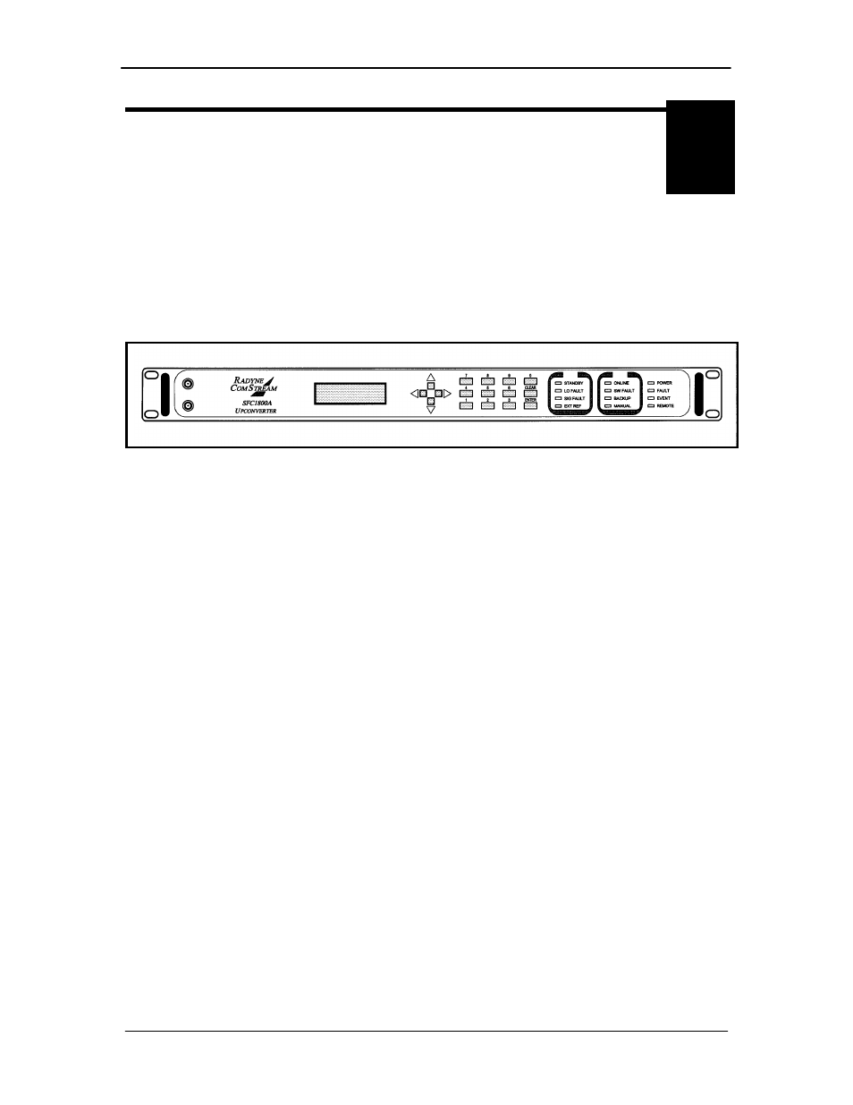
This manual discusses the Radyne SFC1800A Synthesized Frequency Upconverter (Figure 1-1).
This high-quality, rack-mountable satellite upconverter is intended for use in medium-to-large
earth station installations where multiple carrier uplinks need to be established. The SFC1800A
Upconverter is ready to be configured into a variety of backup switch configurations, which
include 1:1, and 1:N (where N is a maximum 8) configurations.
Figure 1-1. SFC1800A Upconverter Front Panel
The SFC1800A Upconverter is a DBS-Band, 125 kHz resolution synthesized satellite upconverter
capable of converting either a 36 MHz bandwidth, 70 MHz IF input or optionally a 72 MHz
bandwidth, 140 MHz input to a DBS-Band uplink in the range of 17.30 - 18.40 GHz.
All of the configuration, monitor, and control functions are available at the front panel. Operating
parameters such as frequency, channel, gain, gain offset, and switch settings (backup only) can
be readily set and changed at the front panel. Additionally, all functions can be accessed with a
terminal or personal computer via a serial link (RS-232, RS-485, or Ethernet) for complete remote
monitoring and control (M&C) capability. Extensive fault monitoring with masking capability,
along with time and date stamped event storage is available.
The units monitor local oscillator (LO) phase-locked loop faults in the converter at all times during
operation. If a fault is detected, the converter immediately goes into the Standby Mode. If
multiple converters are configured to provide backup protection switching, a summary fault will
signal the backup, which will put itself online and restore the failed circuit.
The RF Hardware consists of a broadband synthesizer, a fixed frequency phase locked oscillator,
and the first and second converter modules. The broadband synthesizer provides the
synthesized local oscillator for the conversion from L-Band to RF output. The LO that tunes from
14.80 - 15.90 GHz performs this conversion. The second mixer converts the 70 or 140 MHz IF
input to L-Band. A fixed frequency First IFLO performs this frequency conversion.
A 20 dB gain control attenuator at the L-Band of the second mix module controls the power out of
the converter. This attenuator is capable of 0.1 dB resolution through a software linear
interpolation of 1 dB calibration values.