0 sfc1800a upconverter connections, 1 power, 2 10 mhz ref in (j4) – Comtech EF Data SFC1800A User Manual
Page 67: 3 10 mhz ref out (j3)
SFC1800A Synthesized Frequency Upconverter
Rear Panel Interfaces
TM111 – Rev. 1.0
5-1
Rear Panel Interfaces
5
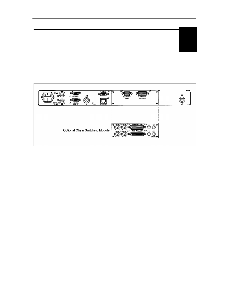
5.0 SFC1800A Upconverter Connections
All SFC1800A Upconverter connections are made to labeled connectors. Any connection to an
SFC1800A Upconverter must be made with the appropriate mating connector. Refer to Figure 5-
1 for the various connector locations.
Figure 5-1. SFC1800A Upconverter Back Panel
5.1 Power
Located on the left side of the SFC1800A Upconverter Rear Panel is the AC Power Input
Connector. This connector is an IEC/EN60320/C13 Power Entry Module. The unit is powered
from a 100 – 240 VAC, 50 – 60 Hz source. Maximum unit power consumption is 50 W. The
switch turns power on and off to the unit. A chassis ground connection can be made at the #10
size stud located between the IF (J2) and Ethernet (J9) connectors.
The Power Cord/connector for the SFC1800A Upconverter is a supplied item.
5.2 10 MHz Ref In (J4)
The Reference Input is a 50 Ohm BNC-F connector (J4) allows the operator to synchronize the
synthesizer of the converter to an external 10 MHz reference. When an external reference is
properly applied to the reference input, the external reference LED will illuminate on the front
panel.
5.3 10 MHz Ref Out (J3)
The 10 MHz Reference Out (J3) is a 50 Ohm BNC-F Connector that provides a 10 MHz square
wave, 50 Ohm AC coupled reference output signal at 0 dBm. In normal operation (no external
reference) this output is synchronous with the internal high stability 10 MHz reference.